A solar panel mount is described here for two household solar panels mounted on a Mariner Yachts 36 staysail ketch. The panels are Panasonic HIT high efficiency solar panels available in 335 Watt and 340 Watt versions at the time of purchase. The panels are 62.6" by 41.5" by 1.6" high.
The boat measurements, constraints, and placement is described in the Solar Panels web page. The placement of feet and overall dimensions reflect the constraints described there. The rendering to the right reflects the placement relative to the masts and booms.
This design follows a set of more elaborate designs. Prior solar mount designs had too many bends and a few pieces that would have proved very difficult to fabricate. Some of the prior designs had compound bends, bends of 180° and pieces bending back onto themselves.
The goal of this design was to make the design easy to fabricate. The number of bends was reduced and eventually the design was simplified so that there are a minimal set of 90° bends.
Two residential grade solar panels will be used, mounted with the long side of the panels fore and aft. The panels are mounted below tha main boom and on either side of the centerline. The position of the panels is pushed outward as far as practical to create a gap between them. This gap is slightly wider than the width of the cockpit sole. Four vertical posts and feet are placed on the side decks as far outboard as practical.
The gap between panels serves two purposes. Pushing the panels out insures that at any given time at least one panel will not be in the shaddow of a mast. Another benefit is the space above the cockpit sole is less impeded due to the gap between panels. Athartship tubing near the mizzen mast and above the companionway would minimally impeded the space above the cockpit. Very tall crew would need to duck. When seated in the cockpit the panels will be overhead, providing shade. The frame extending forward will provide a useful and sturdy handhold when exiting the cockpit to go forward on the side decks.
Another consideration is interference with jib tracks, jib sheets, and other running rigging led aft to winches in the cockpit. The vertical legs have to be far enough aft to avoid jib sheets and have to be pushed close to the toe rails due to the jib tracks. The gap between vertical legs needs to be kept clear to avoid interference with winches mounted on the coamings and to avoid the winch handles when in use.
A crash bar was considered, forward of the panels and above them. The purpose of the crash bar would be to protect the panels from damage if the topping lift was released with sails down. After careful measurement is was determined that there simply is no room for a crash bar. This problem can be avoided by using a boom kicker, a fiberglass pole approximately parallel to the boom vang that acts as a spring holding the boom up at all times.
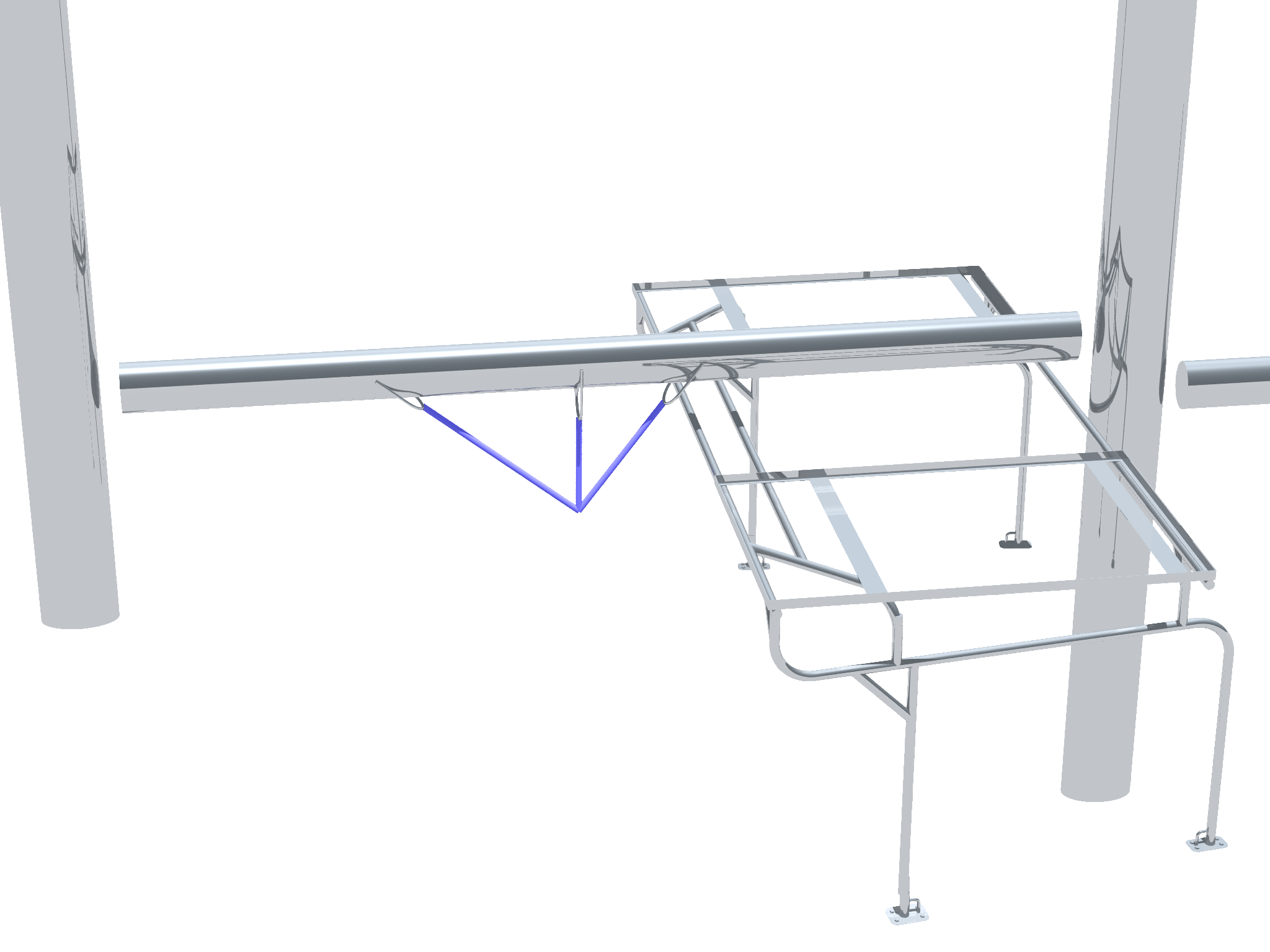
The solar mount frame is planned to be made up of four assembled pieces, two horizontal upper assemblies and two nearly identical vertical side assemblies. The purpose of making four pieces is to allow assembly and disassembly and transportation of the pieces by pickup truck. A rigid roughly 10 foot by 6 foot assembly with legs would be difficult to move. Using separate pieces will also make it easier to snake the solar panel wires. The feet are also separate so that once bedded to the side deck the feet can remain when the solar panel mount is removed.
![[img: Solar Mount Assembly with Spars]](simple-mount.png)
As designed and rendered, all tubing is 1½" diameter, the panel frames are made from 1½" by ¾ angle stock, the base is made from plate stock, and ½" rod stock is used on the base. The tube, angle stock, and plate stock is assumed to be heavy gauge stock to provide adequate strength. As drawn it is 3/32 stock but standard guage stock of adequate strength should be used. Smaller stock could be used if the metal fabricator considers it to be adequately strong with the up to 10' spans. The short diagonal support pieces could be made of smaller diameter stock if that makes fabrication easier and yields no significant reduction of strength.
There is a limit to the accuracy of measurements on the deck of a boat made with a tape measure. This and the varying slope of sidedecks makes it hard to provide a drawing with measurements from which the entire mount can be fabricated with no intermediate steps to check measurements. Therefore an iterative process will be needed with steps including fabrication of small parts, placement, and measurement before larger parts can be assembled.
The separate welded assemblies as rendered to the right are shown disassembled with a small vertical separation between assemblies in the renbering. The vertical connections are made by welding a smaller diameter short section of tubing to the lower part of the joint extending up into the upper assembly. Putting the weld on the lower peice should reduce or eliminate water intrusion. The upper tubing should easily slide over this smaller diameter tubing if the fabrication has been done carefully. The solar panel frames will be mounted to the upper assemblies using nylon bolts to allow them to break away if struck from the side rather than have them bend and destroy the solar panels.
![[img: Panel Frame 3D Rendering]](panel-frame.png)
The dimensions of the Panasonic HIT high efficiency solar panels are 62.6" by 41.5" by 1.6" high. A frame with outside dimensions of 63" by 42" can be made of 1.5" angle stock of about 3/32" thickness. Ideally this could be 1.5" high angle stock with a smaller dimension, such as ¾". This would leave space for a few nylon or rubber washers and leave the aluminum solar panel frame sticking up only slightly from the stainless steel frame.
The a teak frame will be built around the metal frame. This will allow the corners to be rounded. A simple teak grating with window bug screen will be built under the panels to prevent accidental scratches to the panel underside which can allow water intrusion and cause failure of the panel.
The tab plates used to mount these panel frames to the athwartship peices can be cut but should be welded on later when positions of these tabs are confirmed. These will likely be where the wood frame is attached as well.
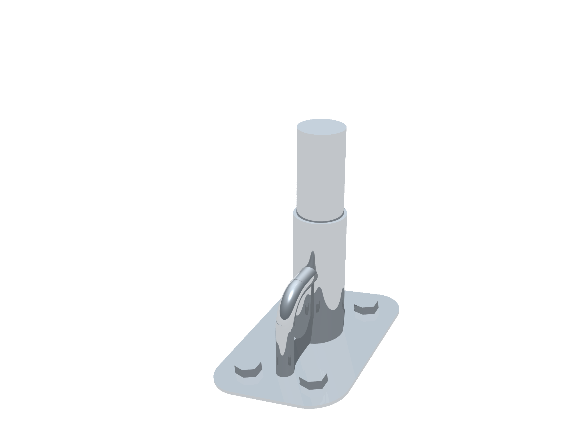
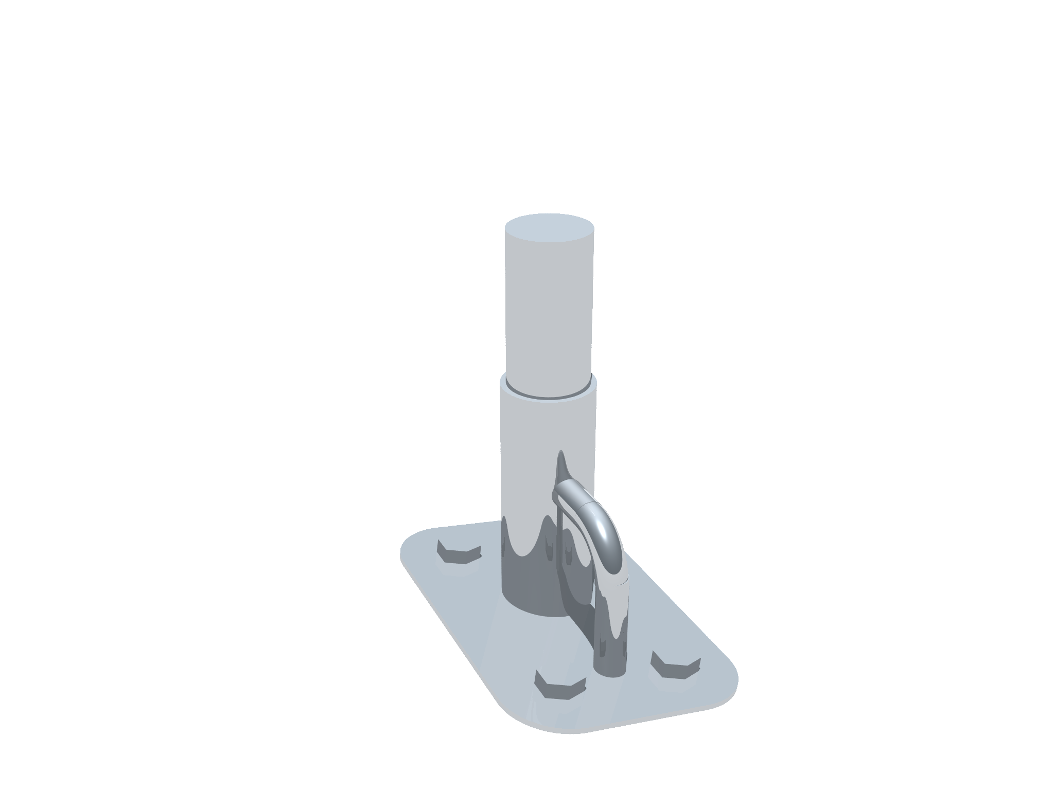
It is very important that the vertical tubes in the forward and aft feet on each side are parallel in order to make it possible to mount the lower assembly on it and remove it later without needing excessive force to do so. All four vertical tubes should be parallel and a simple way to accomplish this is to use a plumb bob to make each as close to vertical as possible.
![[img: Fore and aft lower bars]](fore-aft-bars.png)
The fore and aft lower bars can only be fabricated after the feet are set in place and measurements taken. The forward vertical has no bends and need only be cut to size. The aft vertical has two bends. All pieces can be made from stock slightly longer than needed leaving a small excess then cut to a more exact length on site.
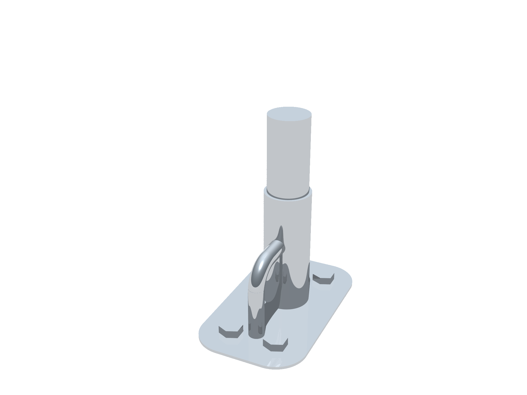
![[img: Foward Upper Assembly]](athwartship-bars.png)
The aft feet are about 6" aft of the front of the mizzen mast, just forward of the drain next to the mizzen chainplates. The aft end of the solar panel mount is intended to be mounted 6" forward of the front of the mizzen mast. With a 9" bend in the lower assembly that leaves 3" forward of the bend to mount the uprights, plus the radius of the tubing (¾" for 1½" OD tubing). The added radius amount will put the center of the tube at the outside of the panel frame (minus any wood frame).
A 15/16" hole should be drilled in the horizontal bar where the upright will be welded. This hole is to pass solar panel wiring (see the Solar panel wiring section).
The final welding can then occur in a shop as long as the joints are parallel to each other and perpendicular to the horizontal bar. To be sure of a fit, the joints can be spot welded on site or at least checked for angle to the horizontal bar (should be exactly perpendicular) and scored on site. Spot welding on site is preferred.
The forward upper assembly needs to be high and forward but below the boom. It needs to be high because the crew will already have to duck when stepping on the bridgedeck and then entering the companionway and because the crew will have to duck when moving between the cockpit and the sidedeck, stepping over the coaming. This bar will have to be forward to be as far forward over the companionway as possible without interfering with the main sheet.
On each side of the forward upper assembly a support peice is added. This can be cut on the shop and it and the vertical strut on the fore and aft peice can be welded on site. Each support peice has a strengthening peice that can also be cut at the shop and welded on site.
If all goes well the feet and the two lower and two upper assemblies should slide together easily. A few more steps will be needed after this initial mechanical assembly.
A few welds were deferred and if not already welded need to be completed. The two athwartship horizontal bars, one each on the aft upper assembly and forward upper assembly, can be initially cut oversized and then cut on site to the exact size.
The athwartship horizontal bars should be capped on the ends to prevent wind from whistling (creating a very large low pitch flute). The aft caps should be removable to provide access when routing wiring (see Solar panel wiring below). If a lathe is available plugs can be made.
The entire assembly should be sufficiently rigid as designed. Diagonals on the lower assemblies should prevent flexing fore and aft. Diagonals on both upper assemblies should prevent flexing athwartship. The two horizontal bars of the lower assemblies and the two upper bars of the upper assemblies form a nearly rectangular trapezoid (narrower aft). The 45° tubing on the forward upper assembly should be sufficient to prevent distortion of this trapezoid. If the aft end of the trapezoid can be distorted, then similar 45° supports can be added aft.
The solar panel wiring must be added. The best place for the wired to enter the boat is through the port aft foot. The wire can enter the panel frames through the aft upper assembly horizontal tube.
The solar panels come with a short section of wire and large waterproof connectors that are standard for solar panel installation. Wires terminated in this connector on one side need to be passed through the tubing. The connectors inside the hull of the boat need not be the same. If the connectors are small enough they could fit through a large hole with gromets inside the framing at the 90° joints they will have to pass through. The panels are rated just under 72 VOC and just over 6 ASC. A connector rated 120V and 10A would be more than sufficient. The connectors on the panels have to be rated for the maximum system voltage that the panel is rated for, in this case 600V.
A small diameter hold can be drilled from above clear through the deck. A very large diameter hole drilled from the bottom of the foot. The hole in the deck can be enlarged to accomodate PVC conduit. The conduit should extend far above the foot to prevent water intrusion and then glassed into the deck.
There are two joints where holes will need to be drilled to allow wires to be passed through a 90° weld joint. In both cases a long drill bit will be needed if holes are not predrilled. Long metal cutting bits are available up to ¾" by 18" but cost well over $100 for large sizes. Predrilling 15/16" holes prior to welding would allow a ¾" ID grommet to be installed.
A light messenger line can be snaked through the wiring holes of each of the two assemblies, followed by a more rigid electrician's snake or other stiffer and stronger line. The four wires and connectors can be passed through each piece individually. The connectors can be staggered for an easier fit. The assemblies can be installed after the wire is run through each assembly.