This design is no longer being considered due to it being too complex to easily build. It has too many critical bends and alignment difficulties. A simpler solar panel mount design replaces this design.
A solar panel mount is described here for two household solar panels mounted on a Mariner Yachts 36 staysail ketch. The panels are Panasonic HIT high efficiency solar panels available in 335 Watt and 340 Watt versions. The panels are 62.6" by 41.5" by 1.6" high.
The forward feet athwartship spacing is wider than the aft spacing but the upper assembly is rectangular. Two design choises were considered, called the narrow design and the wide design. In both designs the top part of the frame built from tubing is rectangular even though the aft feet are spaced closer together than the forward feet. In the narrow design the upper assembly is as wide as the aft feet spacing. In the wide design the upper assembly is as wide as the forward feet spacing. The wide design is shown here.
A drawback of making the upper assemby wider is having some metalwork extend beyond the beam of the boat, though far from the widest part of the boat. A mishap with a tall bollard might cause damage but might also cause the boat to harmlessly heel without bending the frame.
Advantages of the wide design are an increase in the gap between panels and less interfere with the winches and movement forward along the side decks. The wide design may also prove slightly easier to build.
The narrow design uses a set of tubing to reach the wider forward vertical posts that is called the "wings" for lack of a better term. The wide design uses a double bend in the aft vertical tube to create an offset.
In either design there is about a foot of tubing on either side extending aft of the panels. Part of this is a 90° bend from horizontal to vertical to avoid sharp corners. This puts the aft legs back closer to mizzen sidestays and avoids interference with winches. Part of this tubing extends aft of the mizzen mast but not to the mizzen side stays which are slightly swept back. The aft athwartship tubing and panels are further forward to avoid the mizzen mast.
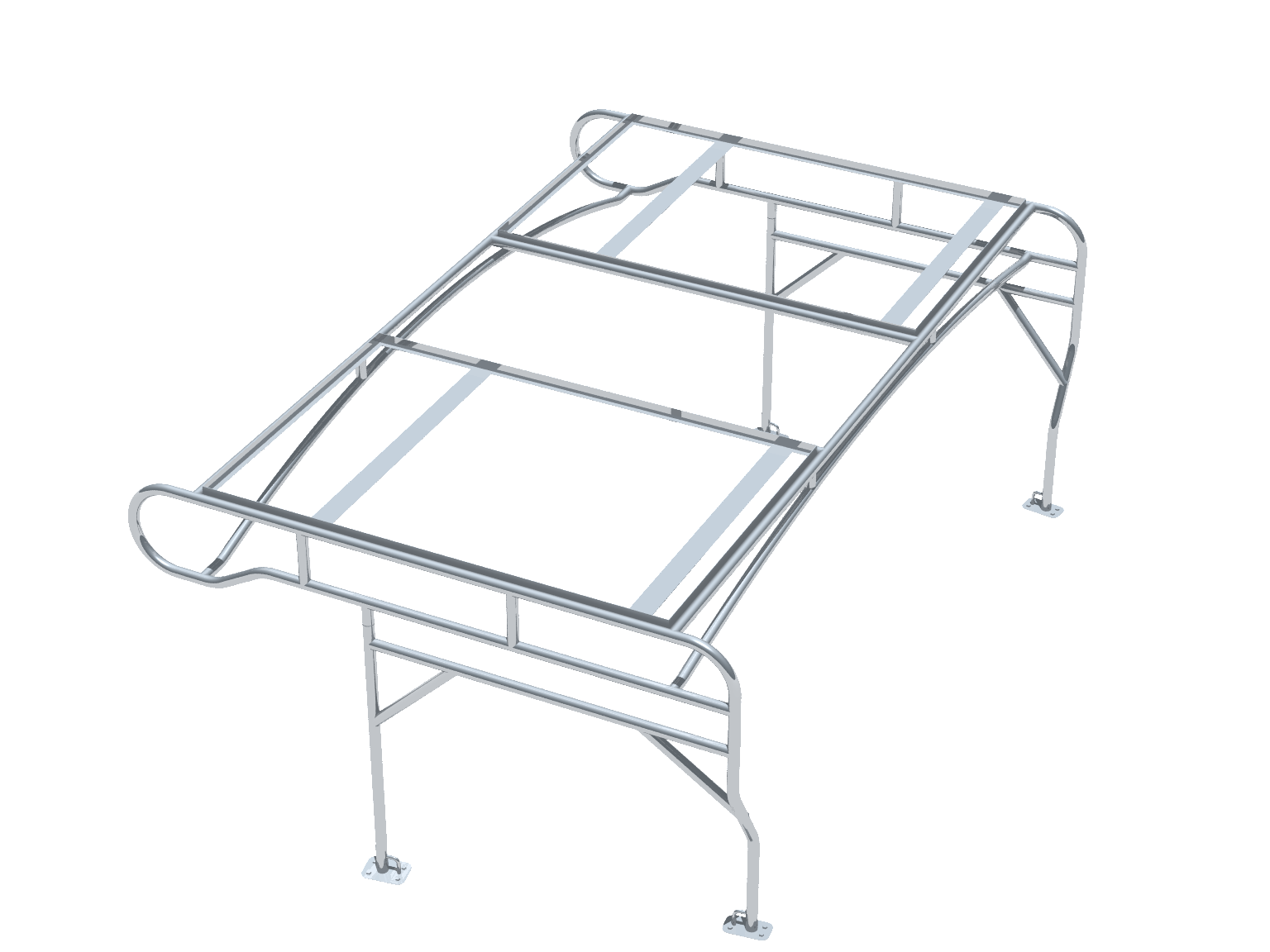
The solar mount is planned to be made up of three assembled pieces plus four feet. The three assembled pieces are a horizontal upper assembly and two mirror image vertical side assemblies. The purpose of making three pieces is to allow assembly and disassembly and transportation of the pieces by pickup truck. The roughly 10 foot by 6 foot upper assembly will be much easier to transport without the roughly 5 foot legs attached. Using three pieces will also make it easier to snake the solar panel wires. The feet will be bedded to the hull and are separate from the vertical assemblies to allow them to be removed, keeping within height limits when the boat is moved on land.
The upper assembly has many bends and quite a few individual pieces. A set of subassemblies are described in roughly the order that they can be constructed.
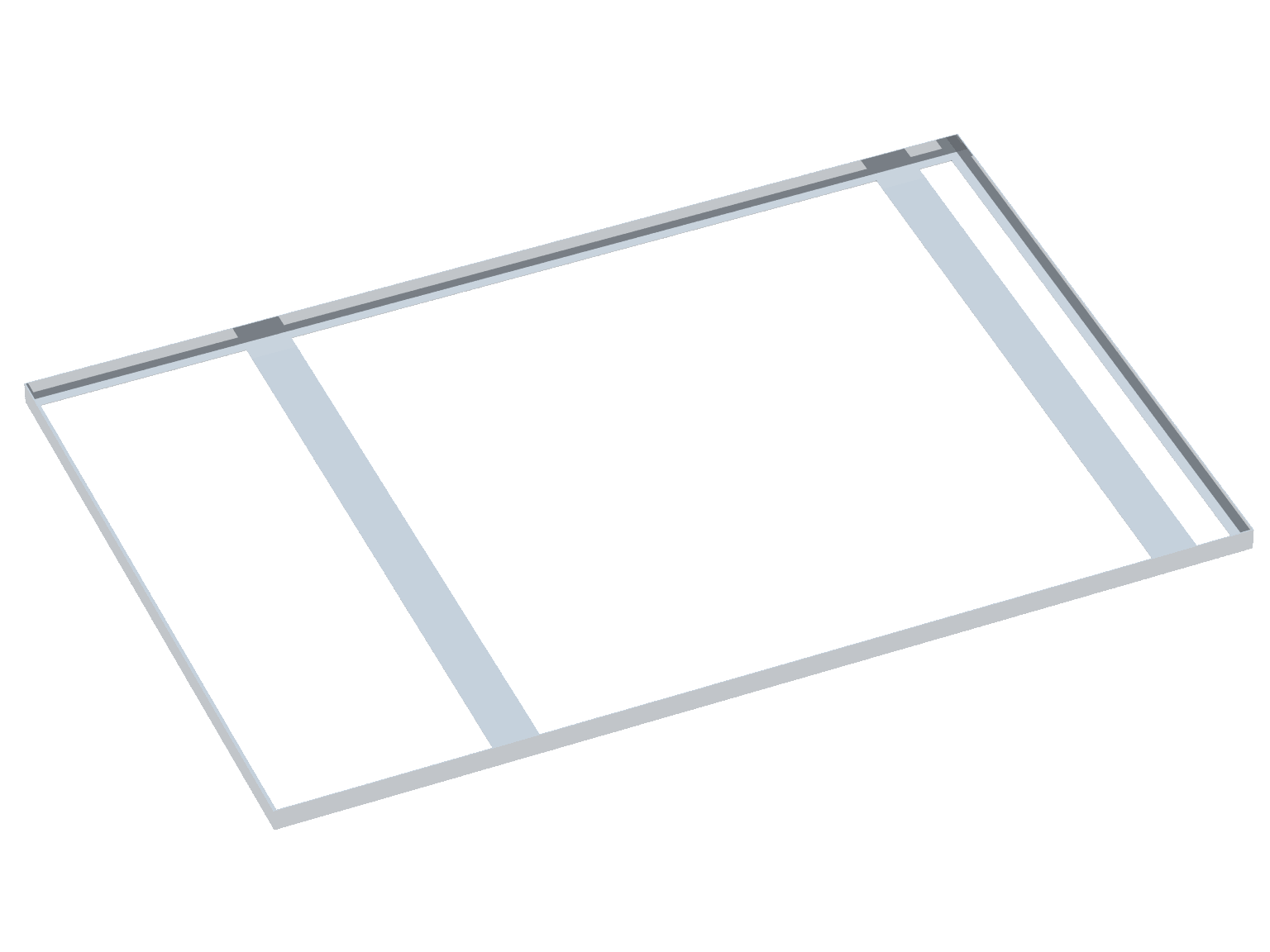
The dimensions of the Panasonic HIT high efficiency solar panels are 62.6" by 41.5" by 1.6" high. A frame with outside dimensions of 63" by 42" can be made of 1.5" angle stock of about 3/32 thickness. Ideally this could be 1.5" high angle stock with a smaller horizontal dimension, such as ¾". Oversizing the frame slightly leaves space for a few nylon or rubber washers and leave the aluminum solar panel frame sticking up only slightly from the stainless steel frame.
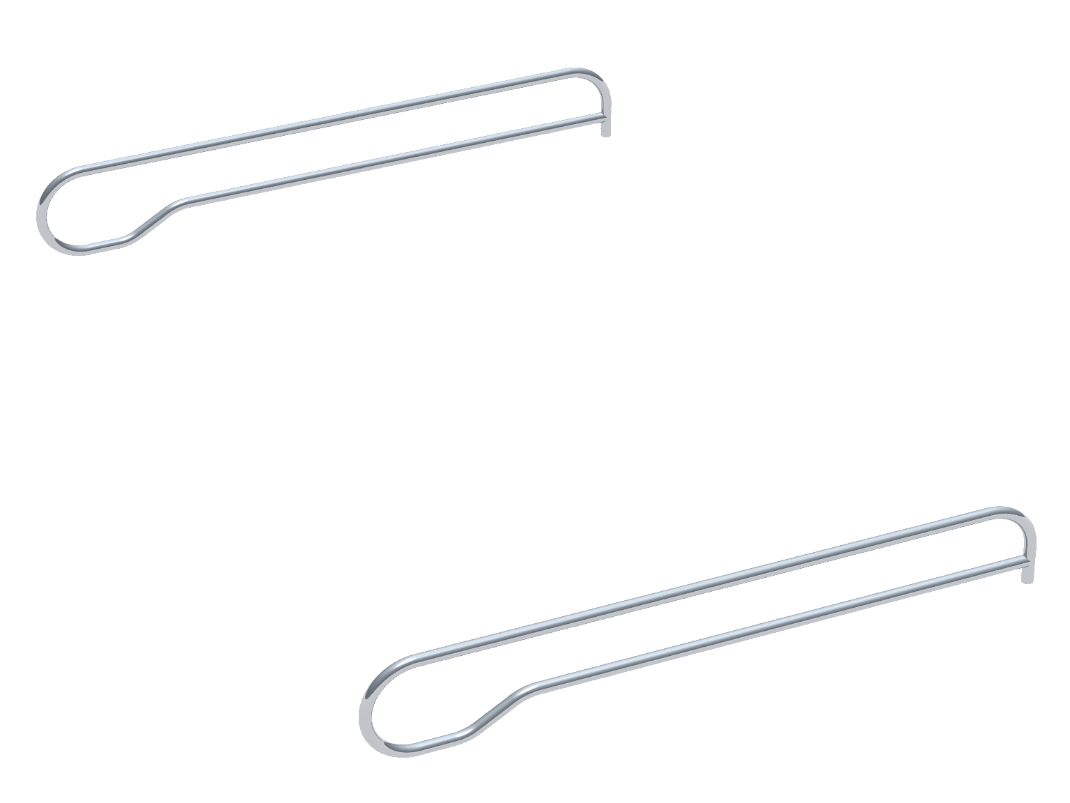
There are two identical upper assembly side bars, one on each side. Each side bar has four bends, one 90° bend, one 180° bend, and a pair of opposing 30° bends to create an offset. If suffiently long stock is available, each side tube can be made from a single piece. The bend back onto itself will make this piece difficult to fabricate.
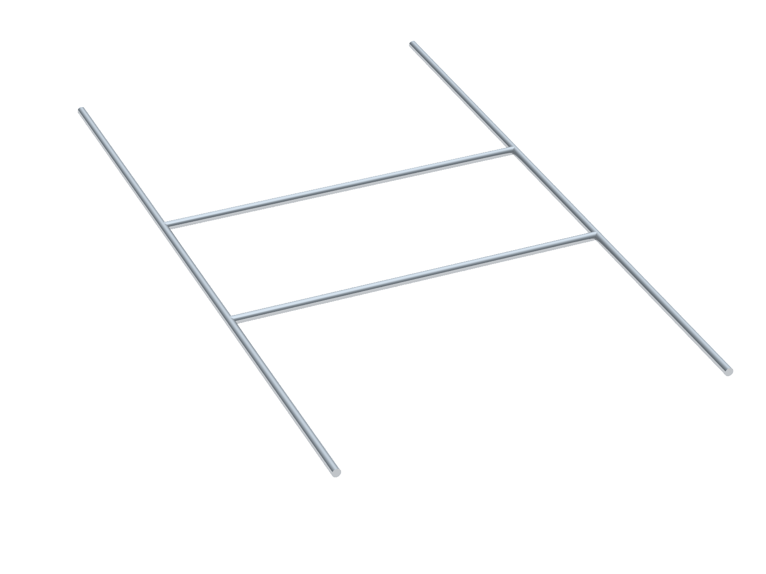
The upper solar panel support bars consist of four straight tubes. These surround the angle stock panel frames on three sides with a gap in the middle. The side bars surround the panel frames on the remaining side. The aft athwartship tube can be cut first. The aft tube should be welded in place first as far back as possible on the side tubes without welding it on the aft 90° bend. The panel frames can then be welded in place on two sides. Then the two inner fore and aft tubes can then be cut and welded in place. Finally the forward athwartship tube can be cut and welded in place.
The aft traveller main sheet boom bail will have to be moved forward on the boom. The original position is 38" aft of the mid main sheet boom bail. As drawn it has been moved forward 19" from its original position. This puts the aft boom bail 88" from the gooseneck.
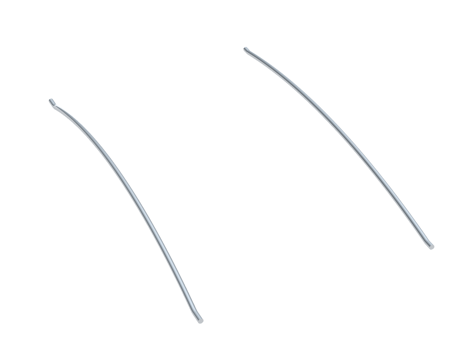

The forward and aft lower athwartship support bars each have a long radius bend that offsets the tube up and each is used with a vertical support to support the long athwartship span of the upper tube. The bend both creates somewhat of an arch and improves headroom. The forward tube has a deeper bend than the aft tube.
The long bend in the lower tubes could cover nearly the entire lenghth of the tube with two optional tigher reverse bends at each end, or could cover the entire length. As drawn the reverse bends are used. It may be slightly easier to put a long bend in a piece of long tube stock and then cut to fit. The goal is to create a brace below the top bar with about two inches between the two and short vertical struts to create triangles and strengthen the long span. Each tubes can simply be bent over a long length of stock until the desired depth of the bend is acheived.
As designed there are eight short vertical support pieces and two short struts used to connect to the forward part of the lower assembly. The shorter of the support pieces could be smaller diameter tubing or the same diameter. Two of these pairs of supports exist to reinforce the long spans fore and aft and on either side. Another two of these pairs of supports exist to reinforce the long spans athartship.
The forward portion of the upper assembly is cantelevered relative to the lower units. If this is not sufficiently strong then a leg can be added to either side of the companionway after installation. There are small feet for the former dodger frame and it should be possible to reuse these. This would probably be best measured after initial installation.
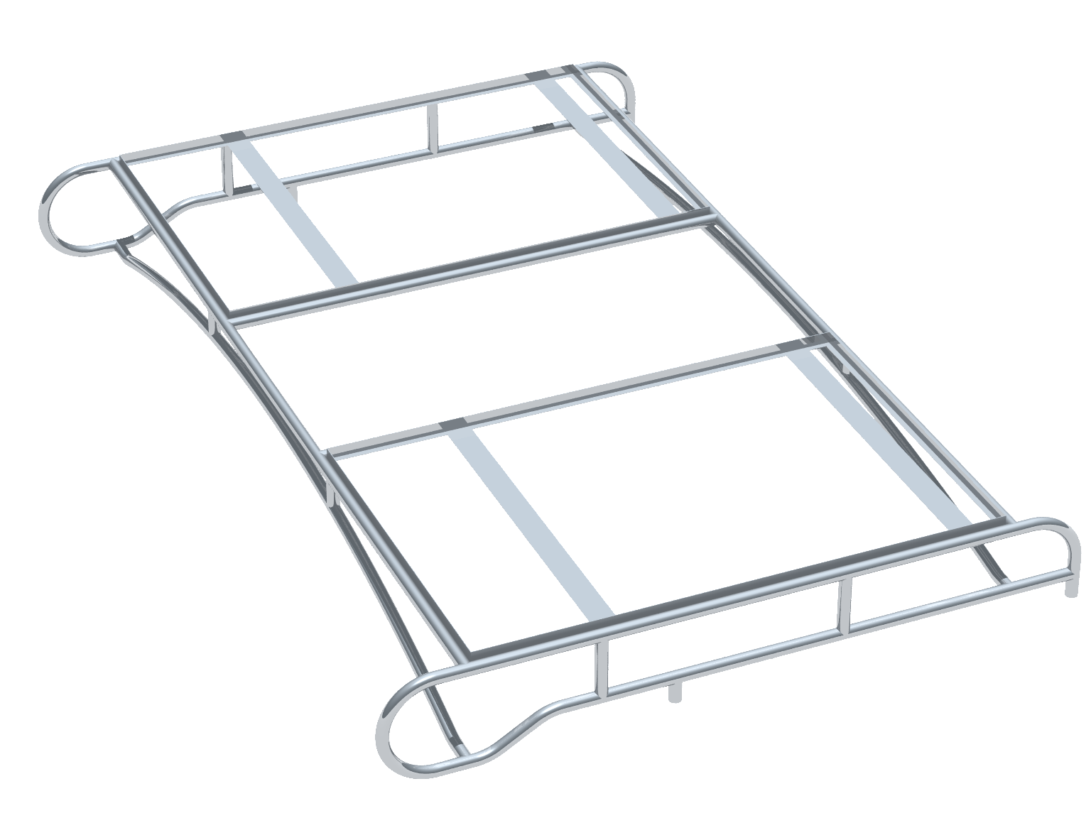
The complete upper assemby is the sum of the pieces described above. It is suggested that they be fabricated and welded together in the order described above: panel frames, side bars, upper bars, lower bars, and small reinforcement pieces. Some variation in fabricated dimensions is likely so the order of assembly is planned so that small variations can be taken into consideration in the next subassembly.
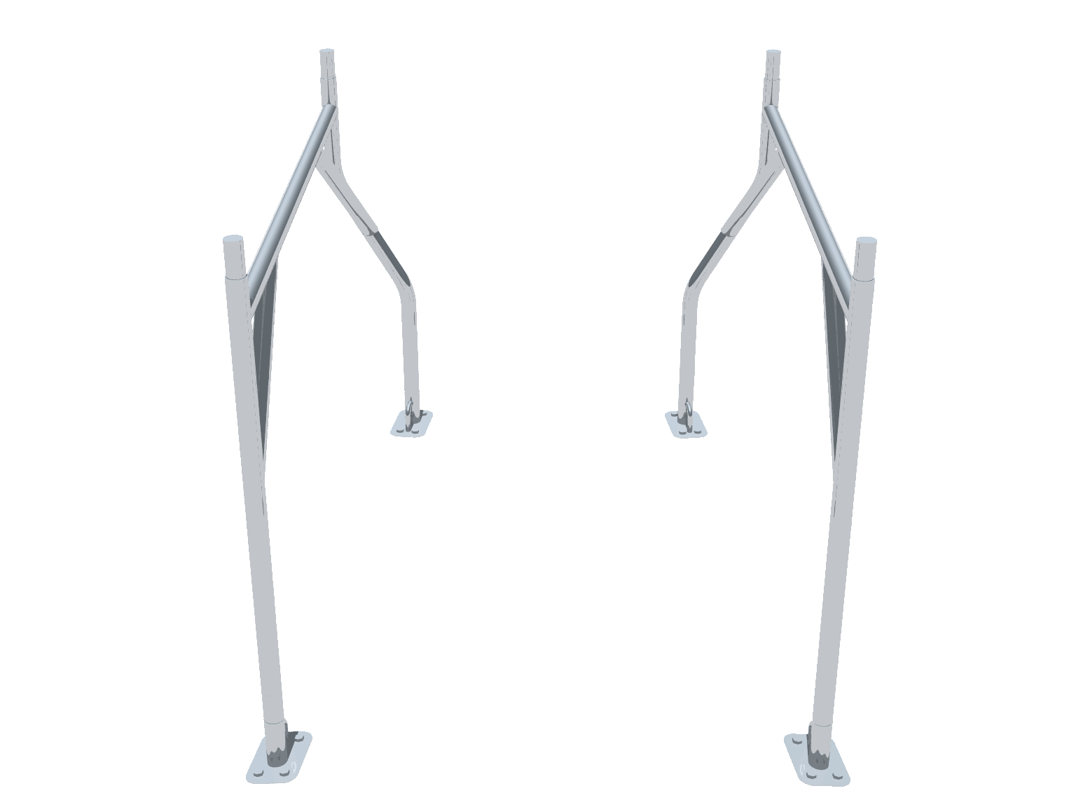
There are two mirror image lower assemblies. Each lower assembly consist of two legs, a horizontal tube, and two 45° diagonal support tubes, plus plus the four base plate assembies (feet). The forward leg is a straight tube. The aft leg has a double bend to create an offset. The lower assemblies are shown to the right with feet attached.
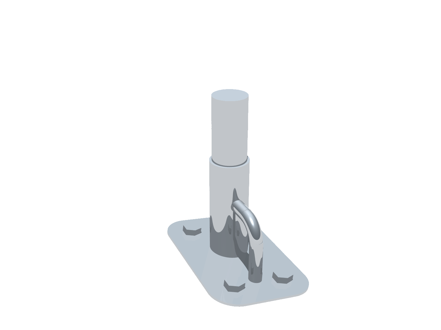
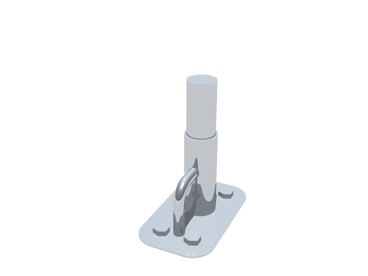
The lower assembly vertical tubes, aka legs, are designed to be vertical where they meet the upper assembly and vertical where they meet the feet. The base plate assembly, aka feet, are not mounted on a level surface. As drawn, the feet are separate assemblies so that if a small measurement error is made only the feet would need to be changed.
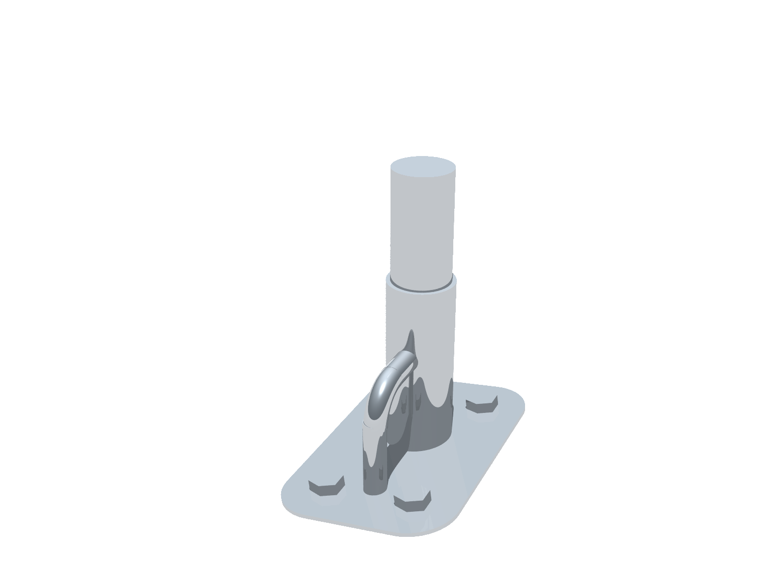
The boat side decks slant so that water drains outward toward the toe rails. The aft feet are mounted on a narrow surface just forward of a side deck drain. This surface is nearly level side to side allowing the two aft feet to be identical. The surface under the forward feet slants outward and slants slightly aft. The aft foot is one inch narrower due to limited space aft as the side deck narrows.
The three images to the right show port and starboard forward feet, and the identical aft feet. The tilt in the forward feet is barely visible in the images.
As designed and rendered, all tubing is 1½" diameter, the panel frames are made from 1½" by ¾ angle stock, the base is made from plate stock, and ½" rod stock is used on the base. The tube, angle stock, and plate stock is assumed to be heavy gauge stock to provide adequate strength. As drawn it is 3/32 stock as drawn but standard guage stock of adequate strength should be used.