
Battery Box Design
There are three battery banks: 48V, 24V and 12V. The 12V and 24V banks have two batteries each. The 48V bank has eight batteries arranged as four parallel strings of two 24V batteries in series. The Batteries web page describes the selection of batteries and the overall battery bank design.
Two batteries are placed in a single battery module. In the 24V and 12V modules the batteries are connected in parallel. In the 48V modules the two 24V batteries are connected in series. The Battery Installation web page describes the space available for batteries, general battery module design, and battery module placement.
Overall Design and Construction
This is the second major iteration of this design. When the decision was first made to use terminal posts they were put on top which added too much height. A second measurement of the space the modules were to fit in revealed that the 1¾" terminal posts needed to be mounted on the front or back of the modules. With posts on the front there will be a bit more of a challenge to building the complete solution so that cables can't possibly touch each other during install of the battery modules.
Overall Design
The 24V batteries are 7" wide, 13½" long, and 8½" high not counting the slighly raised landing for the battery posts. The battery posts are a threaded hole and bolt. The bolt can be removed to install the batteries as long as there is plenty of room around the posts to add connections once the battery is in place. The 12V batteries are ½" shorter at only 13" and can be put in the same sized module with a ½" spacer or in a ½" smaller module.
The battery boxes will be constructed with pressure treated 2"x4"x8' lumber rip cut to smaller dimensions plus ½" plywood for the floors. To cushion the batteries ⅛" high density closed foam polyurethane will be used on the floor, sides, and back.
When building a rough prototype some issues were encountered. The modules have to be constructed from the inside out so that screws can be added. Otherwise the drill and in some cases even a screwdriver can't be fit. With that revelation the construction order is now:
- center divider,
- top assembly,
- bottom assembly,
- front, back, and sides.
At least one side of a module will have to be removed to install the batteries. The cables within the module can then be connected. If the batteries bind on the foam when installing it might be necessary to remove front and back panels, install the batteries and then screw the panels back in place.
Dealing with a Tight Fit
The design allows for the thickness of ⅛" high density closed foam to keep the batteries in place. To make it easy to install the batteries in the box a full ⅛" will be allowed except to reduce width slightly, the foam will be compressed to 1/16" thick in the battery long dimension which is the box width dimension. To preserve the wood after construction two coats of white bilge paint will be applied before adding the polyurethane foam. This will add some thickness and compress the foam a bit more in both dimensions.
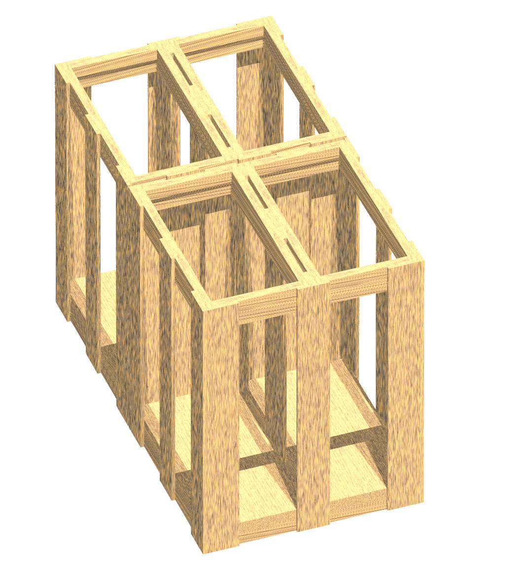
The top and assembly has two layers of wood strips that are overlapped and held together by glue (marine epoxy) and four screws, one in each corner, plus screws along the length. The bottom assembly has a single level of wood strips and is glued and screwed to the plywood battery floors. Between the two floors are a vertical center divider. The top and bottom assemby will be glued and screwed to the center divider. One side may be shared by two modules, creating a two module wide single assembly that is less wide by one side panel thickness.
Variations in the bottom layer will be made to distinguish the 12V vs 24V vs 48V modules with platforms designed so that only the correct module type will fit correctly when set in place. The position of the terminal posts will also be different enough so that it would be very difficult to install the wrong module type at any position.
The center divider, front and back will be ¼" thick. The sides will be 3/16" thick to keep the module width narrow enough. The width of the module will be the 13½" battery length plus two for layers of foam compressed to 1/16" adding ⅛" and the width of either side. The total width is 14".
Sharing a side would make fitting two modules into a 28" wide space a certainty. Rather than combine two boxes into on that would weigh over 100 lbs, the slats on the back side of each box will be offset such that when placed back to back there are six non-overlapped 2&¼quot; slats separated by a &¼quot; gap with the boxes themselves overlapped by the thickness of the slats. The batteries, wood, and wiring should weigh less than 60 lbs per box with the center framing making a reasonably good lift handle.
Each battery is 7" wide. Foam on either side adds four layers for ¼" total, plus divider, front and back at ¼" each. The total length is 15" plus just under 2" for the terminal posts.
Wiring
Each battery string will have two MRBF fuses mounted on a battery post. Separate charging and load battery cables will be used, connected to terminal posts mounted on the module assembly and to the MRBF fuses on the positive side. Wiring is described in the Battery Installation web page and the Battery and Electrical Wiring web page.
Cutting Battery Box Framing and Assembly
At the time of this design there was a partial sheet of ½" plywood and three 8' lengths of (nominal) 2"x4" pressure treated lumber (plus a lot of other scraps, both large and small) left over from prior projects. Finding these in the garage it seemed reasonable to use these for the battery boxes.
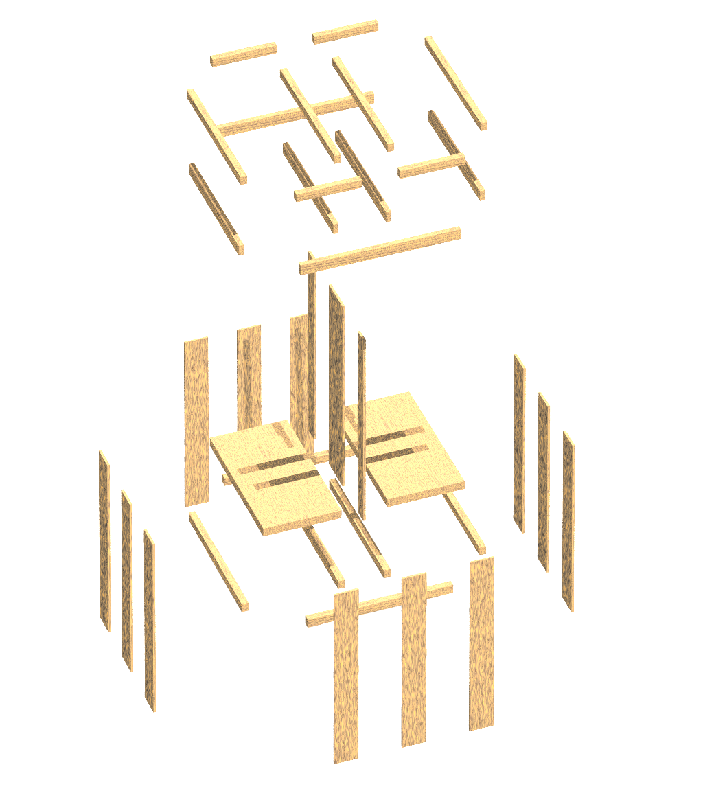

The design became somewhat iterative which is made easier and more accurate with a computer. The same source files used for the images and the video on this page were used to create an inventory of peices needed.
| Battery Box Pieces | ||||
| Assembly | Part | H | W | L |
| center | center | ¼" | 3⅜" | 11½" |
| front | ¼" | 1⅜" | 11½" | |
| back | ¼" | 1⅜" | 11½" | |
| top support | ½" | ⅝" | 13⅝" | |
| top support | ½" | ⅝" | 13⅝" | |
| mid support | ⅝" | ½" | 12⅝" | |
| mid support | ⅝" | ½" | 12⅝" | |
| bottom support | ½" | ⅝" | 13⅝" | |
| bottom support | ½" | ⅝" | 13⅝" | |
| top | top frame | ½" | ⅝" | 13½" |
| top frame | ½" | ⅝" | 13½" | |
| top frame | ½" | ⅝" | 13⅝" | |
| top frame | ½" | ⅝" | 13⅝" | |
| mid frame | ⅝" | ½" | 14¾" | |
| mid frame | ⅝" | ½" | 14¾" | |
| mid frame | ⅝" | ½" | 12⅝" | |
| mid frame | ⅝" | ½" | 12⅝" | |
| floor | floor plate | ½" | 7¼" | 13⅝" |
| floor plate | ½" | 7¼" | 13⅝" | |
| bottom | bottom frame | ½" | ⅝" | 13½" |
| bottom frame | ½" | ⅝" | 13½" | |
| bottom frame | ½" | ⅝" | 13⅝" | |
| bottom frame | ½" | ⅝" | 13⅝" | |
| sides | side board | ¼" | 2¼" | 11½" |
| side board | ¼" | 2¼" | 11½" | |
| side board | ¼" | 2¼" | 11½" | |
| side board | ¼" | 2¼" | 11½" | |
| side board | ¼" | 2¼" | 11½" | |
| side board | ¼" | 2¼" | 11½" | |
| side board | 3/16" | 2¼" | 11½" | |
| side board | 3/16" | 2¼" | 11½" | |
| side board | 3/16" | 2¼" | 11½" | |
| side board | 3/16" | 2¼" | 11½" | |
| side board | 3/16" | 2¼" | 11½" | |
| side board | 3/16" | 2¼" | 11½" | |
| Total dimensions = 11½"H x 14"W x 15¼"L | ||||
Some adjustment was made to thickness and width dimensions of some of the peices to use a small number of stock sizes and get everything so rip cutting the 3 8' 2x4s would produce the needed lumber with a little left over. The results are shown above and in the table below summarizing the total length (rounded up 3") and the number of 8' lengths with fractions rounded up to 1 foot (⅛ of an 8' length). There is a chance that when cutting the long peices there will be left over and the third 2x4 will have to be used.
| Total length needed for six battery boxes | ||
| dimension (WxH) | length | 8' lengths |
| 2¼" x 3/16" | 35' | 4⅜ |
| 1⅜" x ¼" | 12' | 1½ |
| 2¼" x ¼" | 35' | 4⅜ |
| 3⅜" x ¼" | 6' | ¾ |
| ⅝" x ½" | 122' | 15¼ |
| lumber needed if cut perfectly | ||
| board feet = 6.8, 8' 2x4 = 2 | ||
| plus plywood | ||
A nominal 2x4 is actually about 1½"x3½" after the wood is dried at the lumber mill. Fortunately an 8' length is really 8' long or more. The table saw blade makes a wide cut so ⅛" was allowed for cut thickness. All of the peices can be rip cut the entire length of the 2x4 with the one 3⅜"x⅝" piece cut in lengthwise with the longer part rip cut into two 3⅜"x¼" peices and the shorter part rip cut into ¼"x½" and ½"x½" pieces.
After being rip cut and and then cut to lengths the pieces will initially be assembled with wood screws. The assembly should go smoothly although it may not fly together as illustrated in the video. After assembly a set of side pieces will be removed from one side. The front and back may also be removed if the fit is tight. The remaining assembly and individual pieces will be glued and screwed and later given two coats of bilge paint. Then the foam will be glued in place. Once dry the batteries will be installed and then removed pieces screwed back in place (but not glued). Fuses and cables internal to the module will be installed and the module will be ready for installation.