DIY Electrical, Navigation and Instrument Monitoring
Monitoring, archival, and in some cases automated action is needed in two areas. One is the electrical system. The other is navigation and ships instruments. The goals of electrical system monitoring and the state of commercial solutions is discussed in the Battery Monitoring and Protection web page. The goals of monitoring in ship's navigation and instruments is discussed in the Navigation & Communications web page.
Limitations of Commercial Solutions
Many of the commercial solutions for solar charging and other energy products were originally intended for home solar and energy storage systems. In order to allow outdoor use and industrial use some of these products were designed for dirty, somewhat caustic, and wet environments. This meant that they were suitable for the marine environment as well. The products generally supported proprietary monitoring but some, most notably Victron, provided gateway products to support marine specific interfaces, most notably NMEA-2000.
The instruments and displays used in the marine environment evolved from proprietary interfaces to standards defined by NMEA (National Marine Electronics Association). The NMEA-0183 standard used a four wire serial interface that was appropriate for connecting one instrument to one display. NMEA-0183 did not specify a connector and often instrument displays used colored conductors and four spade lugs. Early multifunction displays offered more than one set of spade lugs. NMEA-2000 used CANBUS, a physical interface and link layer originally intended for automotive use. NMEA-2000 provides wires for ground, power, and two differential signal wires and specified a connector suitable for marine use. Many manufacturers embraced NMEA-2000 but used their own proprietary connector, offering expensive cables to interface to the standard NMEA-2000 connectors.
The specifications for NMEA-0183 and NMEA-2000 are covered by copyright and are very expensive to purchase. They have both been reverse engineered with software libraries available for free with various open source licensing.
The choice of CANBUS for NMEA-2000 was not a good one. Lower powered instruments or transducers were powered by the bus. Higher powered devices such as radar and autopilot needed their own power supply. Chartplotters also needed their own power supply and injected power onto the bus allowing a small number of transducers such as a knotlog/depth transducer to be powered by the chartplotter. For more than one or two instruments power had to be injected at more than one place on the bus. This creates loops in the power supply. It also means that if one device taking power off the bus is powered on, they all have to be powered on, including any chartplotters. A solution is to cut the power wires in some of the cables, but not a solution endorse by NMEA. On a commerical ship if one thing is powered on, everything is powered on. NMEA and chartplotter manufacturers never envisioned powering on some NMEA devices but not all.
The NMEA protocols are quite primitive. NMEA-0183 uses ASCII printable characters and is line oriented. The line length is limited to 83 characters including the CR and LF that end the line. NMEA-2000, being based on CANBUS is binary. The payload is called a parameter group. The type of payload is identified with a 29 bit parameter group number (PGN) allowing over 32 million types of messages although well under 100 assigned. The body of the payload is a fixed length 8 bytes. This somehow was thought to be enough by the automotive world. To support longer payloads two methods are used to pack a message across multiple payloads. This is a terrible format but apparently it is the best CANBUS could come up with and NMEA adopted it. The latest NMEA standard is essentially NMEA-2000 over ethernet, ditching the serial bus for something more modern but keeping the arcane protocol.
General Purpose Computers and Data Aquisition
Battery protection, battery monitoring, charge monitoring, and load monitoring can all be provided using a very small general purpose computer, data acquisition modules, and solenoids to support battery protection. Alternately, battery monitoring and charge monitoring can be provided by a small computer and data acquisition modules with battery protection left to commercial products that won't be affected by a failure of the small computer.
The DIY solution requires more work but should yield better results. The biggest risk is that the non-marine components may fail. For battery monitoring this is not a major risk. Components are so cheap that a complete set of spares can be kept on hand. The greater risk may be in battery protection, either failure to prevent depleting a battery by not shutting off, or unintentionally shutting off loads including the chargers for the 24V and 12V batteries. A possible fallback could be manual override switches that bypass solenoids (or bypass the winding side). Solenoid failure could produce similar issues, but solenoids are also cheap and spares can be carried.
These same computers can archive any NMEA data provided by instruments and serve to archive position, wind speed and direction, depth, speed, course, heading, and any other NMEA data available. An integrated GPS can be used to provide position archival even when instruments are off. Other transducers such as indoor and outdoor environmental monitoring, water temperature thermocouple, ambient light sensor and three axis accelerometer and gyroscope are available and may prove useful.
Single Board Computers
A single board computer (SBC) is a small fully funtional computer that is based on a single board. Most use small low power system on a chip (SoC) processors which incorporate most major functions of a computer onto a single chip. Some smaller peripheral chips, power management, and connectors complete the board. Most SBC use the ARM64 architecture (aka aarch64) used in Apple PCs and laptops (but not Apple's chips). Some use the AMD64 architecture used in most PCs and laptops. A small but growing number use the very new RISC-V open processor architecture.
Some SBC use the 64 bit architecture used by AMD and Intel (known as the AMD64 architecture since AMD used it before Intel). These boards mostly use recent low powered Intel chips (AMD is stronger in the server market rather than low powered processors). The AMD64 processors tend to be more powerful than the ARM64 processors but draw far more power and generate far more heat which is evident by the very large heat sinks and fans on the AMD64 chips. They also require more support chips but they almost all support GbE or higher, lots of RAM, SSD storage, and one or more 3.5" hard drives. Prices range from $100 to about $300 plus case, fan and power supply.
The ARM64 architecture is the basis for many products. Low end chips are used in cell phones as well as for the Raspberry Pi and similar products. Apple has embraced the ARM64 architecture by making their own high end ARM64 processors and including them in PCs and laptops. The SBC products, Raspberry Pi being one, are based on low end to mid range performance chips from various sources. These include Amlogic (US), Texas Instruments (US), RockChip (China), Allwinner (China), Realtek (Taiwan), Broadcom (US) and others. Some user may prefer to avoid processors made in China due to other unrelated Chineese products incorporating security back doors in the past. Broadcom SoC chip specs are covered by NDA which is a major drawback. Broadcom SoC are used by Raspberry Pi which are used widely enough that drivers exist for most operating systems. These are not as fast and support less memory and perpherals than the AMD64 based SBC but draw far less power and so are more appropriate for monitoring devices that are intended to operate 24 hours a day. Prices range from $50 to $300 plus case and power supply and optional fan.
RISC-V is a relatively new open processor architecture offering royalty-free open-source licenses. RISC-V started in 2010 at the University of California, Berkeley and was transferred to the RISC-V Foundation in 2015 and then RISC-V International, a Swiss non-profit entity, in 2019. Most semiconductor companies that support RISC-V are relatively new and their SoC chips are quite new. Operating system support is not mature quite yet.
Some older SoC are based on the 32-bit armv6 and armv7 architecture. SBC based on these chips can start as low as $10 with power draw as low as 10W (max). Some 64 bit SBC are a bit more expensive but are power optimized with power draw as little as 5W (newer processors are more power efficient).
The Raspberry Pi line is the best known small SoC. Raspberry Pi has a 40 pin GPIO (general purpose I/O) header. A set of daughter cards are available that sit on top of the Raspberry Pi and perform various functions, GPS, accelerometer and gyroscope, data acquisition, etc. Raspberry Pi calls these shields. Other SoC have imitated the Raspberry Pi and even if using a larger or smaller card, provide a compatible 40 pin header. This allows them to use the same shields and there is an independent market for shields. Shields can be stacked up to the limit of the power supply for the SBC.
Microcontrollers
Another type of processor is a microcontroller. These are very anemic but low power processors intended for industrial control. Many microcontroller based cards are based on the Amtel AVR family of single chip microcontrollers. For example, the popular Arduino is an open source hardware and software set of designs with recent boards based on the ATmega328 microcontroller. These have multiple built in A/D and D/A and digital inputs and outputs. Various pins can be programmed to serve as either digital or analog input or output. Newer Arduino boards use different processors.
The microcontroller based boards are slow, particularly the smaller ones. The Arduino Nano and compatibles have clock rates in the 10s of MHz rather than small single digit GHz for SBC (so 100 times slower). The power draw is also more than 100 times less, typically 80 mW rather than 10W (and less in low power mode where a 3.3V power supply is used). The boards are also tiny with the Nano less than 44x18 mm (less than 1¾x¾") by 5mm high (under ¼"). These and compatible boards have 4-20 ADC which can be used to measure boat voltages and currents. Measuring current will require external Op-Amps.
The Arduino boards also have daughter cards. Arduino calls these modules. Another company, Adafruit , has boards compatible with the Arduino boards. Adafruit seems to be focusing on the Arduino Nano compatible boards, which Adafruit calls "feathers" (5g therefore light as a feather) and the daughter cards are called "wings" (terminology seems backwards). Some of the feathers have CANBUS so could be used as NMEA data loggers for NMEA-2000. The CANBUS requires 5V and increases the power draw of the cards. There is also a small daughter card known as a "pal" that uses 7 pins of the header but only provides the CAN differential transciever but not the controller. The CANBUS wing provides both.
The Adafruit feather boards are typically under $20 though some are as high as $25-$30. Some excel in providing a large number of ADC. Others have benefits such as supporting CANBUS. Others have slots for microSD cards for data logging. Within a single enclosure (waterproof plastic case with metal lid to allow heat transfer) multiple feather boards could be housed. These can communicate with each other to log data in the absense of a SBC. When an SBC is powered on the logged data can be moved to the SBC for longer term storage on SSD or disk drives.
Single Board Computers Manufacturers
The primay candidates as of 2020 were the Pine64 Rock64 SBC with waterproof case or Pine64 Rock64Pro SBC with either waterproof enclosure or NAS casing to support an SSD drive. The Rock64 would need an external USB SSD which would not fit in the waterproof case. Another possibility is a Polycase Waterproof enclosure.
A lot has changed since 2020. Capability of SBC has gone up but so has price. All offer 64 bit processors with some offering 32GB-64GB of RAM and M2 and SATA ports and GbE and in some cases two 2.5GbE. Many of the boards are now industrial rated. Many of the same players are in the market such as BeagleBoard , HardKernel (ODROID boards) , Pine64 , and Banana Pi . Orange Pi also exists but is based in China. The AllWinner and RockChip processors are also a Chineese design. There are also some new players in the market such as TinkerBoard made by ASUS.
ADC Accuracy and Voltage Range
There are some limitations. The A/D for most of these board are 12 bit providing about 0.25% accuracy at best. For example measuring 0-60V would only be accurate to 15mV and 0-300A would be accurate to 75mA. The 50A shunts used for charging or smaller loads could measure as currents with a precision of 12.5mA.
The A/D pins on most boards are 0-5V or 0-3.3V. An external voltage reference can be used for more accurate and less temperature sensitive measurements. This will require resistors to reduce 0-60V (48V), 0-30V (24V), or 0-15V (12V) to 5V or 3.3V for a voltage measurement. Resistors and an op-amp will be needed to bring 0-50mV up to 5V or 3.3V. Fairly inexpensive 1% tolerance resistors can be used with a per pin calibration. This may result in some thermal drift, but hopefully the resistors will each rise the same percentage and keep critical ratios almost constant.
Higher precision 16-bit ADC are available in separate packages, interfaced using SPI, a serial interface available on nearly all SBC and most microcontrollers. Some of these allow 25mV and 55mV inputs voltages due to onboard Op-Amp and precision resistors. The built-in Op-Amp and precision resistors may be a good solution for measuring the 50mV voltage on a shunt measuring current, however these can be expensive.
Sampling of Commercial Products
The availability of products is transient. This list was first created in 2020. Some entries were added or changed in 2025 but not all links were checked so some may be stale. As products are purchased a new section will be added indicating completed or partially completed work.
SBC based on AMD64 aka x86
All 64 bit processors from Intel and AMD use the architecture called AMD64. Intel had bet on their on Itanium architecture but abandoned it when it failed in the market and adopted the AMD64 architecture. Intel did not want to call it AMD64 and so called it x86 (extended 86, a reference to the products using the 80386 to 80686 naming). A line of SBC based on AMD64 aka x86 from HardKernel includes the ODROID-H4 PLUS with an Intel Alder Lake N processor with 8 cores (N97), 4 SATA ports for disks, up to 48GB DDR5 RAM, HDMI and DisplayPort, 2.5GbE, 4 USB, NVMe for SSD. The SBC is $139 but comes with no DRAM. Adding 32GB DRAM adds $95 to the price.
SBC based on ARM
There are many SBC based on the ARM architecture. These would be used for medium term data logging being able to support much greater storage than the microcontroller based cards. They can run Linux or FreeBSD unlike the microcontroller based cards which run a very simple standalone kernel and have limited functionality. HardKernel offers a reasonably priced SBC based on the US made Amlogic S922X Processor. The ODROID-N2+ with 4GB RAM sells for $83. It has interfaces needed to interface microcontroller based cards, namely I2C (inter integrated circuit). There is also GbE to interface more capable systems. DRAM memory is small at 4GB, but huge compared to microcontroller based cards. Low speed storage for software images is eMMC and SD card. There is no NVMe for SSD or SATA for disks but external storage such as an external SSD could be interfaced using USB 3.0. Power consumption with heavy load is estimated at under 6W, with 6.2W in bursts and 2.2W at idle but a 12V 2A power supply is recommended. These can be powered on automatically to offload data from microcontroller based cards or left on 24 hours/day consuming 2.2W most of the time. This is 52.8 Wh/day if idle. Only periodically offloading data from the microcontroller cards would likely take under 100 Wh/day.
Microcontroller based cards
Although avoiding Chineese based processors may be wise, the microcontroller based cards are not exposed to the Internet or to any modern form of networking, unless WiFi or Bluetooth are supported and enabled or unless ethernet hardware has been added. The Espressif ESP32 is a microcontroller designed and manufactured in China and so is suspect. It is however a very capable chip. The Adafruit HUZZAH32 – ESP32 feather board is a board supporting this processor. Some of its advantages are 3 SPI interfaces, 2 I2C interfaces, and 12 ADC inputs, though these are only 12 bit ADC. It is a 240MHz processor with 520kB integrated SRAM and no DRAM. It has a USB to serial converter used to make its USB-C port look like a serial card and support a convenient development interface, but no general USB support. Adafruit feather wings can be added. It has 4 MB flash but onboard flash is a poor means of data storage.
The Adafruit Feather M0 Adalogger is based on the Atmel ATSAMD21, designed in the Netherlands. It contains a 48MHz ARM Cortex-M0+ CPU, 256kB flash, 32kB SRAM (no DRAM), native USB, 10 channel 12 bit ADC, I2C, SPI, and a microSD slot. It draws less than 1.7W peak, so under 41Wh per day and likely half that. The SD slot can hold a large SD and serve as interim data logging storage.
The Adafruit Feather RP2040 is based on the Raspberry Pi, designed in the UK. It contains a 125 MHz RP2040 32-bit Cortex M0+ dual core CPU. It has 8MB flash and 264kB RAM. It is faster, has more memory, and more on-chip flash than the Feather M0. It also draws less than 1.7W peak. It has 2 SPI and 2 I2C. The 2 I2C allow one to be used to communicate to the SBC as slave and the other to its peripherals as master. It has only 4 input 12 bit ADC. It is not officially supported by Arduino software environment but said to have good unofficial support. A version of this card, the Adafruit Feather RP2040 Adalogger has a microSD slot.
Two other Adafruit cards are of interest. The Adafruit Feather 328P based on the Atmel ATmega328p. The Adafruit Feather 32u4 Bluefruit LE is based on the Amtel ATmega32u4. It has Bluetooth LE (low energy) which is not of interest. Both cards have a slow processor and are less capable than the cards mentioned earlier. Each has has one SPI and one I2C.
These microcontrollers all have 12 bit ADC. To get 16 bit ADC or better external ADC chips will be needed.
Relays and Solenoids
The digital output pins in SBC or microcontroller GPIO headers can drive reed relays which can in turn drive solenoids. These can be used for the battery protection solenoids. For charging loads, voltage threshholds of both the charging source battery and the voltage of the charged battery can be considered.
Some low power relays and solenoids that can be used include the MICTUNING 12V 5 Pin Waterproof Relay Harness Set - SPDT Bosch Style Automotive 40Amp 30 Amp Relay with Heavy Duty 16AWG 14AWG Pre-wired Harness 5 pack and for higher power Cole Hersee products should be available for Defender on special order. It would be best to get three of the 24V solenoids and have one as a spare or for use with AC/heat or other large load. Unfortunately their solenoid line are only rated up to 225A at 48V (10.8kW). They do have 60V 400A contactors in their high voltage contactor line.
The digital outputs of GPIO pins cannot drive the coils of the high powered relays or contactors directly. A GPIO pins can drive a reed relay with 5V which drives a low power relay at 12V which drives a high powered relay or contactor coil at 12V.
Shunts
Bogart Engineering Shunts are availabe in 100A, 500A, and 1000A versions. These are capable of sustaining 75-80% of the rated load for sustained intervals. While inexpensive, these may not designed to be used in a marine environment and may suffer corrosion problems.
Blue Seas Shunts are 50mV full scale. These are designed for a marine environment. They are capable of sustaining 80% of the rated load for sustained intervals.
OP Amps
Quad or Hex op-amps are available and inexpensive. Precision matched resistors could be used or reasonably priced 1% resistors could be used with a calibration done against an accurate DVM. A simple circuit can produce approximately 25-50mV drop across a resistor to calibrate against, for example using an alkaline battery and 40:1 or 50:1 ratio of resistors.
There are plenty of quad and hex op amps. For example, the LM324N/NOPB is a 14 pin DIP low power quad op amp, available from DigiKey for well under $1 in quantity one ($0.75 in quantity 10). The older design with NOPB (no lead in the manufacturing process) is a little cheaper but won't be available for long. Digikey also carries Adafruit and Arduino products and DFRobot who produce Arduino compatible shields.
ADC
The only reasonably priced ADC available through DigiKey with through hole mount is the Cirrus Logic CS5521-AP , a 16 bit 4 input ADC. It costs $3.61 each but minimum quantity is a tube of 84, so $303.24. This is a sigma-delta type ADC.
Mouser lists ADC under Data Converter ICs. They have the Analog Devices AD7705BNZ , a 2 channel 16 bit ADC, $12.63 each in quantity 10, $11.24 each in quantity 25. The also have the Analog Devices AD7706BNZ , a 3 channel 16 bit ADC, $12.90 in quantity 10, $11.45 each in quantity 25. Both are expensive and provide only 2-3 channels. These are sigma-delta type ADC.
The above are all sigma-delta type ADC and the SAR type (successive approximation register) are preferable for DC measurement. Although they are difficult to mount manually and hard to prototype with (no easy way to breadboard), more and better ADC are available in surface mount packaging.
The most accurate reasonably priced chip is from Mouser and it is the Texas Instruments (TI) ADS8688IDBT . This has the lowest DNL (differential nonlinearity) and INL (integral nonlinearity). DNL is a measure of analog amplifier nonlinearity. The latter is related to digital sampling. These are $16.57 in quantity 10 so $165.70. This is an 8 input 16 bit ADC, and so it is less expensive per input than the CS5521-AP. The other chip is the TI ADS8332IPW and ADS8332IBPW, essentially the same chip except the latter, ending in BPW, has a bipolar input. The bipolar input allows measurement in approximately the -2V to 2V range where the unipolar input allows -0.2V to 5.2V if the supply voltage is 5V (as opposed to 2.7V or 3.3V). DigiKey only offers the bipolar version, ADS8332IBPW but has a better price of $9.58 each in quantity 10 vs Mouser's $11.92 in quantity 10. Checking the specifications datasheet (68 pages) the ADS8688IDBT is also bipolar input. The unipolar ADS8332IPW from Mouser is the better among these two. The price is $11.93 in quantity 10, somehow a penny more than the bipolar so $119.30 for the 10. This would provide 80 inputs.
There are a few surprises in the datasheet. The ADS8332xxxx can operate with the analog voltage supply VA and the digital supply voltage VVB at 3.3V or 5V. The external reference voltage Vref has to be about 2.4-2.5V and 4V with supply voltages at 3.3V and 5V respectively. The input voltage can be between -0.2V and VA + 0.2V (yielding 0 and max value outside of 0V and VA).
For most Mouser parts if you buy 7 its slightly cheaper than buying 10 but if you buy 8 its cheaper to buy ten. Only three voltages need to be measured, 48V, 24V, and 12V. These don't require a shunt. For each current measurement a shunt is needed and the shunt, at $50 each, dominates the cost. There will likely be more than 5 current measurements but less than 13, so two ADC are needed. If we use a hot spare in the boat and carry 1-2 spare modules we need 6-8 ADC. One or two may be lost to prototyping. They are solder parts and can't be put in a socket and prototyping requires soldering to a SMD breakout board. Add 2 to the 6-8 needed and might as well buy ten. The most expensive component is the shunt and these generally don't fail. A spare of each type of shunt used (50A, 100A, 200A, 500A) should be carried, just in case.
Transducers and Shields
A large number of microcontroller transducers and shields are available. Some sources and products are listed here.
-
Proto Supplies provides a variety of prototyping components. A few shields and many I2C modules are listed in their Arduino, MCUs & IOT and IC Breakout Modules product categories. The I2C bus (Inter-Integrated Circuit) is a simple but slow bus. Most I2C devices use 4 pins, VCC, GND, SCL, and SDA. The SCL and SDA pins (Serial Clock and Serial Data) are defined by I2C. Modules are often described as supporting the two wire serial interface or TWI. These are incomplete implementations of the I2C interface, often only lacking the clock stretching feature.
Modules using the I2C interface include:
- ADS1115 4-Channel 16-Bit ADC Module ($3.95) supports four addresses, 0x48 to 0x4B. Six voltage ranges are supported, from 0-0.256V to 0-6.144V. With the low range of 256mV the step is 7.8125uV and if used with a 50mV shunt would produce 0.003% accuracy without an external op-amp and resistors and without calibration.
- BME280 I2C Pressure Humidity Temperature Sensor Module ($4.95) uses address 0x76 or 0x77 (but hard to change). This module provides one way to measure circuit enclosure temperature to enable active cooling.
- MPU-6050 GY-521 3-Axis Accel & Gryo Sensor Module ($3.95) uses address 0x78 or 0x69. The module also measures temperature for -40°C to 85°C with ±1°C accuracy. This module would be marginally useful to measure cabin comfort such as roll, pitch, and yaw and acceleration when sailing in large seas.
Sensor modules for A/D converter or other interface include:
- TEMT6000 Ambient Light Sensor Module ($1.95),
- DHT22 Humidity / Temperature Sensor Module ($2.95) can be connected to VCC, GND, and any digital pin on the microcontroller board. It measures temperature in the -40°C to 125°C range with ±0.5°C accuracy. This can be used to measure circuit enclosure temperature to enable active cooling.
- MAX6675 Thermocouple Temperature Module w/ Probe ($6.95) can be used to measure 0°C to 80°C temperatures. Accuracy is ±3°C. It uses the SPI interface and so requires three digital pins. The MAX6675 Thermocouple Temperature Module ($3.59) is the same module without the probe and can be used with an inexpensive thermocouple.
- DS18B20 Waterproof Digital Temperature Sensor ($3.59) measures temperatures in the -55°C to 85°C with 0.5°C accuracy. It uses Vdd, GND and DQ which is connected to a digital pin. This is a DS18B20 chip inside a waterproof enclosure.
Adafruit offers a CANBUS feather ($19.95) with a Raspberry Pi microcontroller. They also offer a CANBUS feather wing ($12.50) which can be mounted on top of any Adafruit feather. The feather wing requires some soldering.
A set of relay modules is available. These use one digital pin per relay. They are rated for up to 15V load at 10A. They could directly drive low current 12V loads (well under 10A) or could drive solenoids for 24V loads and/or higher current loads. Each relay coil draws 70mA when energized. The light sensitive relay module is an alternative for use with light deactivated lights such as the anchor light.
- Relay Module 5V x 2 Relay w/ Opto-isolation ($2.49)
- Relay Module 5V x 4 Relay w/ Opto-isolation ($4.95)
- Relay Module 5V x 8 Relay w/ Opto-isolation ($7.95)
- Light Sensitive LDR Relay Module 12V ($2.95)
Various products can be used for to help cooling of the circuit boards or control fans for power electronics enclosures.
- TEC1-12705 Thermoelectric Peltier Cooling Device ($5.95) is a 12V 5A max (4A typical) 1.6"x1.6" cooling module.
- TEC1-12706 Thermoelectric Peltier Cooling Device ($4.95) is a 12V 6A max (5A typical) 1.6"x1.6" cooling module.
- W1209 Temperature Controller Module ($3.49) is a standalone 12V temperature controller that can be used to drive fans in areas where power electronics is installed. The XH-W1219 Temperature Controller Module ($3.95) is the same but displays both measured temperature and temperature threshhold.
-
Adafruit has a wide variety of products, many for the education and beginners, and many very gimicky. Their shields are mostly for the Arduino Uno. There is a wide selection of Adafruit breakout boards but many are not of interest at all. There is also a wide selection of Adafruit displays that could prove useful. These are small displays 1" to 7" using OLED, TFT, LCD, eInk. Some use I2C or SPI. Some are designed as feathers.
The RA8875 Driver Board for 40-pin TFT Touch Displays - 800x480 Max uses SPI and can drive a 40 pin TFT display. This includes the 5.0" 40-pin 800x480 TFT Display without Touchscreen, or the 7.0" 40-pin TFT Display - 800x480 without Touchscreen.
Some smaller integrated TFT displays are driven by SPI and usually have microSD slot. The breakout card is on the back of the display. These tend to be small. Some examples are the 1.8" Color TFT LCD display with MicroSD Card Breakout - ST7735R, the 2.0" 320x240 Color IPS TFT Display with microSD Card Breakout, and the 2.2" 18-bit color TFT LCD display with microSD card breakout.
The Adafruit TFT FeatherWing - 3.5" 480x320 Touchscreen for Feathers is designed to have a Adafrui feather mounted on the back.
Monochrome OLED displays are bright with high contrast but expensive for the size and lower resolution. The OLED display also needs to be turned off when not in use to avoid dimming the display. The Monochrome 2.42" 128x64 OLED Graphic Display Module Kit is one such display. The board on the back can communicate with I2C or SPI.
Another display type is eInk or ePaper. The 24-pin display can be driven with an Adafruit eInk Breakout Friend with 32KB SRAM using SPI or with an Adafruit eInk Feather Friend with 32KB SRAM mounted on a feather. The 2.13" Flexible Monochrome eInk / ePaper Display - 212x104 Monochrome or 2.9" Flexible Monochrome eInk / ePaper Display - 296x128 Monochrome are displays using this connector. The 24-pin eInk / ePaper Extension Cable 0.5mm Pitch - 25cm Long can be used for more flexibility in mounting. Some of the same displays can be purchased with breakout friend mounted on the back such as Adafruit 2.13" Monochrome eInk / ePaper Display with SRAM - 250x122 Monochrome and also Adafruit 2.9" Red/Black/White eInk Display Breakout - THINK INK and Adafruit 2.7" Tri-Color eInk / ePaper Display with SRAM - Red Black White the latter two displays not offered separately. One display, the Adafruit 2.13" Monochrome eInk / ePaper Display FeatherWing - 250x122 Monochrome is also offered as a feather.
The Adafruit sensors catagory has many sensors, a few of interest. There are GPS modules packaged various ways. The Ultimate GPS Module - 66 channel w/10 Hz updates - MTK3339 chipset is just the GPS module with no breakout board or other components. The Adafruit Ultimate GPS Breakout - 66 channel w/10 Hz updates - Version 3 is a breakout board with a CR1220 coin cell holder. Output is NMEA 0183, 9600 baud default, 3V logic level. A SMA to uFL/u.FL/IPX/IPEX RF Adapter Cable can be used to connect to a GPS Antenna - External Active Antenna - 3-5V 28dB 5 Meter SMA to improve GPS reception. The Adafruit Ultimate GPS FeatherWing provides the same GPS module on a feather wing and can also use an external antenna.
The Arduino and Adafruit components are also available from DigiKey. Digikey and Mouser are good suppliers of ICs, sensors, passive component and just about anything needed for PC boards.
Op amp and resistor circuits for shunts
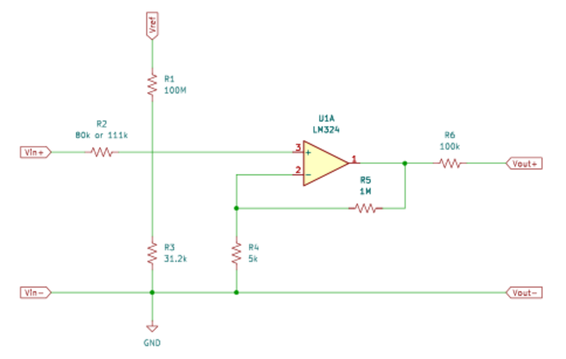
One place where Op-Amps and and resistors will be needed is where current can flow in both directions. Due to regen in the 48V load side current can flow in either direction.
For the 48V load if we assume that the maximum load is 15kW which at 50V is 300A then a 500A shunt is needed. This would be 30mV on and shunt where 500A produces 50mV. If maximum regen is 1kW that is -20A which means -2mV across the shunt. The ADC wants to see 0V to a stable reference voltage, Vref. This can be accomplished with the Op-Amp circuit below.
The ADC and most other components can operate at either 3.3V or 5V. Most microcontrollers can operate at either 3.3V or 5V.
Using the Op-Amp circuit, we have the following equations.
The Op-Amp (+) voltage is:
The Op-Amp (-) voltage is:
Substitute:
and
and
We get:
and
The Op-Amp has very high gain so we can asume
Therefore
The reference voltage for the TI ADS8332IPW, a SAR ADC, is in
the 4V to 4.4V range if used with a 5V VCC. The TE
REF3440QDGKRQ1 voltage reference produces 4.096V. If we
express this in mV then
In the first case we had 30mV at the shunt and about 4.1V
output. If we express these in mV then
and
Substituting we get:
In the second case we had -2mV at the shunt and 0V output. If
we express these in mV then
and
Substituting we get:
Therefore:
Substituting
into the first equation and dividing by 2048 we get:
Therefore:
The effective gain of the Op-Amp feedback circuit is set by which can be arbitrarily set to to allow a 1MΩ resistor and 5kΩ resistor to be used. The gain is 201.
From this point on numbers will be to three significant digits.
The value of
yields
and
For
and
the following applies
and
If is set to 31.2kΩ then and
The reference voltage for the TI ADS8332IPW, a SAR ADC, is in
the 2.4V to 2.55V range if used with a 3.3V VCC.
The TE REF3425QDGKRQ1 voltage reference produces 2.5V. If we
express this in mV then
In the first case we had 30mV at the shunt and 2.5V output.
If we express these in mV then
and
Substituting we get:
In the second case we had -2mV at the shunt and 0V output. If
we express these in mV then
and
Substituting we get:
Therefore:
Substituting into the first equation and dividing by 1250 we
get:
Therefore:
The effective gain of the Op-Amp feedback circuit is set by which can be arbitrarily set to to allow a 1MΩ resistor and 5kΩ resistor to be used. The gain is 201.
From this point on numbers will be to three significant digits.
This yields and
For
and
the following applies
and
If is set to 31.2kΩ then and
The very large resistors can be hard to find at a reasonable price and in lots less than 1,000 and close to the value specified. The value of can't be too small. The values of were chosen to make the large resistor affordable and while keeping the value of high enough. That sum is about 100MΩ. One supplier has 100MΩ resistors (SEI Stackpole HMC2512FT100M ) in quantity 10 for $3.57. Unit price drops with higher quantity. For example, quantity 100 is $23.20. A 31.2kΩ resistor (YAGEO RT0603DRE0731K2L) is $0.28 in quantity 10 and $1.33 in quantity 100. A 82kΩ resistor (YAGEO RC0603FR-0782KL) is $0.09 in quantity 10 and $0.82 in quantity 100. A 111kΩ resistor (KOA Speer RN73H2BTTD1113F50) is $2.08 in quantity 10 and $9.13 in quantity 100. These are all 1% tolerance or better. The RT0603 resistors connected to the shunt are rated for 75V use. The RN73H2B resistors are rated for 200V use. The HMC2512FT100M is rated for 250V use.
A simpler exercise can be used for other shunts where the voltage only flows in one direction. To take a 0V to 50mV signal from a shunt and produce 0V to 4.1V or 0V to 2.5V a simple amplifier with two resistors is needed. The gain of 82 or 50 would accomplish this. The 1% resistor tolerance will vary the gain as well. A 1MΩ and 13.2kΩ or 21kΩ resistors can be used.
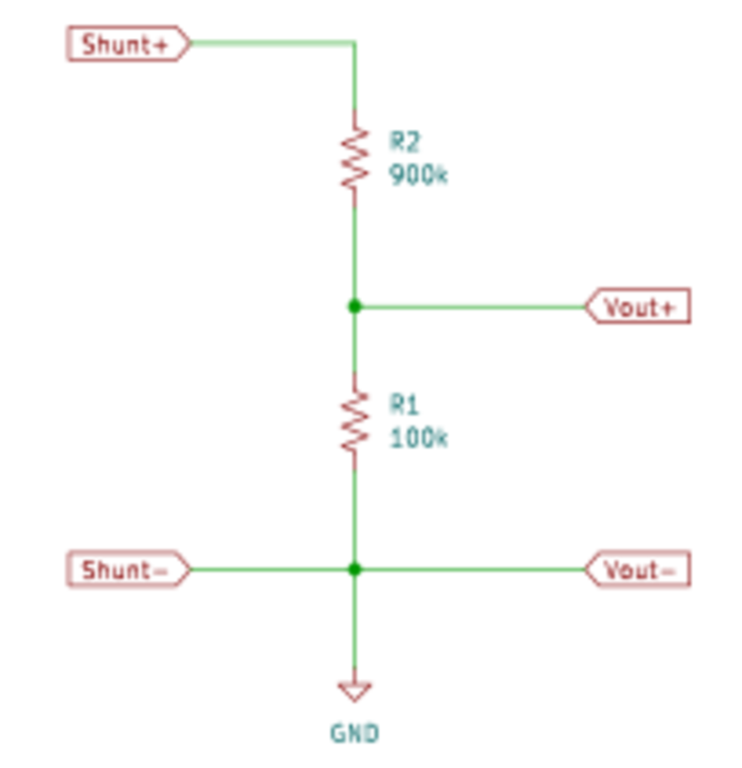
In addition to the shunts, the battery voltages have to be reduced. This is accomplished with the circuit above with resistor values for a 10:1 attenuation. For the attenuation circuits it would be safe to round up 12V to 16, 24V to 32 and 48V to 64. This is above the voltage where the batteries would shut down. Attenuation is . We want and and . If we fix then we can compute the value of as . The set of values for are provided in the table below for a fixed value of
| Attenuation Resistor Values | ||||
| Voltage | Attenuation | R2 value | Vcc = 4.1V | Vcc = 2.5V |
| 16V | Vcc / 16 | 1MΩ | R1 = 344kΩ | R1 = 185kΩ |
| 32V | Vcc / 32 | 1MΩ | R1 = 147kΩ | R1 = 84.6kΩ |
| 64V | Vcc / 64 | 1MΩ | R1 = 68.4kΩ | R1 = 40.6kΩ |
The shunts need to be on the ground side. While it is possible to independently measure the voltage on either side of the shunt and subtract the two, there is a 1000:1 ration of the approximately 50V on the nominal 48V battery and the 50mV across the shunt. This would waste 10 bits of the ADC. It is also possible to use a differential Op-Amp though there would need to be a boosted voltage above that of the shunt plus a differential Op-Amp would be more expensive (a few dollars). Putting the shunts on the ground side makes things a lot easier.
Initial Monitoring Plans
This section will have an increasing level of details as configurations are finalized.
Commercial solutions have the advantage of being off the shelf but the disadvantage of being inflexible and costly. DIY solutions take a lot more planning and work and will require that non-marine components be mounted in at least waterproof if not air tight enclosures. The flexibility of DIY solutions drove the decision to forego using off the shelf solutions.
Overall Plan
Sort term archival will make use of a small SBC. In 2020 this would most most likely be handled by two Pine64 Rock64 SBC each with a USB to SATA interface (available as a dongle) and a small SSD. Smaller SBC might be adequate but the USB 3.0 provides a performance improvement over those SBC with USB 2.0. Now in 2025 a more likely candicate is the ODROID-N2+ with 4GB RAM offering somewhat better performance and lower power draw.
The two SBCs will both be connected to two or more microcontroller boards via serial connection or I2C. The SBC Ethernet (GbE) will be used to interface longer term archival which is normally powered down and to connect the SBCs to each other.
The role of the microcontroller boards connected to the SBCs is to multiplex I2C interfaces to multiple other microcontroller boards or circuits handling data aquisition or driving solenoids and possibly low power displays. The SBC connection will use the microcontroller UART at reasonable speed or use an I2C if the microcontroller has more than one I2C interface (common). The very low speed I2C (10kbit) interface and/or SPI will be used to connect to other microcontroller boards and ICs. CANBUS support could be provided to support NMEA-2000 archival.
Additional microcontroller boards and/or ICs will be used for data acquisition and to drive solenoids.
Redundancy and Spares
The SBC are inexpensive and have very modest power requirements. The microcontroller boards and most transducers are even more inexpensive and draw even less power. For this reason redundancy is built into the design with two of everything that plays an important role. In addition spares will be carried.
There will be two microcontroller boards measuring each voltage (or current which is voltage across a shunt). In a few important roles there will be two solenoids driven by separate microcontroller boards with the solenoids either in series or parallel depending on whether the solenoid NO or NC mode is used and whether a single failure defaults to off or on or control by the other solenoid. In critical roles, such as charging, solenoids there will also have manual override switches with off, on, or auto (likely SPDT with center off), with the auto switch position making use of the solenoids.
Also for the sake of redundancy the two sets of SBC and microcontroller boards should be driven by separate power supplies with a spare available. The power supplies will be low power DC-DC converters to provide 5V or 3.3V.
Power Supplies
The various boards may require nominal 12V, 5V, and 3.3V power supplies. Many boards have onboard voltage regulators that can take 6V to 12V but work best at about 9V. Most boards that take a nominal 12V warn of overheating with 15V or more. Since the 12V bank can vary from under 12V to 15V, a DC-DC converter is the best solution to provide a constant voltage to the more sensitive small voltage regulators on these small boards.
The DC-DC converters should also be waterproof so that they can be mounted outside of the small electronics enclosure to avoid then becoming a heat source within that enclosure. It is harder to find DC-DC converters capable of 4A-6A output at 9V than with output at 5V. It may be necessary to have both for any device that does not have an onboard voltage regulator. A number of waterproof DC-DC converters are available on Amazon from uxcell , KNACRO , SMAKN , and DROK .
It may be that each set of SBC and boards has a 9V and 5V DC-DC converter in the range of 50-100W each plus spares. Many of the DC-DC converters can take 9V-35V input, offering a slight step up if needed and so can be connected to either the 12V or 24V bank. Additional redundancy can be achieved by using both the 12V and 24V banks.
Enclosure and Mounting
A variety of cases are available from Polycase Waterproof enclosures which are rated IP65 or better. The stainless steel cases tend to be expensive but the aluminum cases are reasonably priced. One of the roughly 8"x6" cases with an external aluminum heat sink or with a peltier cooler and heat sink would provide adequate room and adequate cooling.
External connections can be accomodated by either cable pass throughs (cable clams, cable seals, cable outlets) or waterproof multiwire connectors. It might be best to bundle power together, signal (voltages, transducer) together, and solenoid together. Three cable pass throughs and heat shrink tubing to create a waterproof bundle can be used. Alternately multiconductor waterproof cables can be used. The latter may be a better solution but is more expensive.
Cases in the $30-$40 price range (quantity one) are the AN-07F 8.76 x 5.75 x 2.17 aluninum case , the AN-22F 7.87 x 4.72 x 2.95 aluninum case , and the AN-16F 6.29 x 3.93 x 2.37 aluninum case both with mounting flanges, a watertight gasket and IP67/IP68 rating (submersible). The latter two have better placed internal mounting screws. Polycase also has CG1 Black Cable Glands with IP66 rating and at very good prices or CG3 Gray Cable Glands which are IP68 rated and at good prices.
There is a lot of room over the pilot berth that is enclosed and dry and the power supplies and enclosures can be mounted there. This is an area that will be easy to separately ventilate.
Data Acquisition
With three battery banks there are three voltages to be measured. The figure in the Battery, Charging and Load Wiring web page shows 13 shunts. There are a number of places where thermocouples or temperature/humidity transducers could be used to control cooling.
Battery Voltages and Shunts
Voltage and current measurements should be done with 16-bit A/D converters. Up to four of the ADS1115 4-Channel 16-Bit ADC Module can be used with a Adafruit feather microcontroller board.
A single microcontroller board (two for redundancy) could support all of these data acquisition needs but with only one A/D channel to spare. Any other input requiring A/D can use the microcontroller 12-bit (or 10-bit) A/D. Measurement time intervals can be long and made very long using small capacitors and resistors up to multiples of seconds.
Temperature Measurements
Temperatures that may need to be measured include the following:
- external ambient,
- case internal,
- power electronics enclosure,
- refrigeration coil,
- inverter enclosure(s),
- pilot berth,
- forward cabin.
Solenoids
The figure in the Battery, Charging and Load Wiring web page calls for seven solenoids. The two solenoids connected to the stove inverter be a single relay wired to the external power switch input of the two inverters (2 115V inverters) if the inverters support this feature. The galley inverter and any other cabin inverters are not shown in this diagram. For expansion two Relay Module 5V x 8 Relay w/ Opto-isolation board (four considering redundancy) should be used. The microcontroller digital pins need only drive the opto-isolator with external 5V (from the DC-DC converter) used to drive the relay solenoid windings.
Another issue is the number of low power relay wires passing through the waterproof case. A single 12V positive wire (from a 12V DC-DC converter to keep voltage from approaching 15V) can be led into the enclosure reducing the number of wires per relay to the NO or NC wire. The relays can drive very small loads such as LED lighting or drive solenoid winding for larger loads.
Cooling
Most cooling consists entirely of enabling fans or in-line blowers when temperature is high and significantly higher than ambient. For the monitoring electronics a peltier cooler may be used with a heat sink in addition to a fan or blower. The forward cabin may use a blower to suppliment airflow from ports (or when ports are closed due to rain) and will also enable the cabin AC/heat which has its own thermostat. The monitoring electronics has the advantage over the AC/heat thermostat in being able to account for battery bank state of charge.
Internal Case Cooling
The case or cases that contain the SBC and microcontrollers are the only situation for which peltier cooling would be considered. This might be useful in the heat of the tropics but otherwise airflow and perhaps a heatsink should be adequate. Given the low cost, a peltier cooler and heat sink will be added to each case in addition to heat sink directly mounted.
The peltier cooler is 1.6"x1.6". A slightly larger heat sink, such as 2"x2" could be used with heat insulating tape to prevent heat from flowing from heat sink back to the case. For passive cooling a larger heat sink, up to 4"x6" could be used. The heat sinks can be mounted such that they are pressed against the bottow side of the case making it possible to access the top side and remove the top cover without removing the case.
Power Electronics Cooling
Power electronics includes the shore side charger and all of the solar chargers used either for the solar panels or battery bank to battery bank charging. The can be mounted inside an open enclosure designed for passive air flow and designed to keep the electronics dry. An inline blower can be used to provide active airflow, venting hot air out of the two aft horn cowls.
Refrigeration Cooling
The compressed refrigerant can reach 120°F to 140°F directly out of the compressor before being cooled and then led to the evaporator. An efficient water cooled condensor cools the refrigerant to about 15°F above water temperature. The Sea Frost BDXP has a water cooled option which supplements the air cooling. Because the compressed refrigerant gets hot very soon after turn on both the fan for air cooling and the raw water pump are on whenever the compressor is running. The unit has a switch to disable the raw water pump so that the refrigeration can run when the boat is not in the water but no thermostat to keep the pump off when air cooling is sufficient. Sea Frost will be consulted to see if control of the raw water pump has sufficient benefits.
Inverter Cooling
There may be up to five inverters in up to four enclosures. The two 115V inverters for the stove, the much smaller inverter for galley outlets, the small inverter for vanity outlets, and the larger inverter for the AC/heat if installed.
The largest inverters are the two 115V inverters used to provide 230V at high amperage to the stove. These will be mounted in galley cabinetry and will certainly require active air circulation. One or more inline blowers will be used with a thermistor based sensor within the enclosure. The warm air will exit via the two aft horn cowls.
The smaller galley outlet inverter may not need forced ventillation. If put in the same enclosure as the stove inverters the same inline blower would be activated if this small inverter raise the ambient sufficiently.
The loads for the vanity inverter are expected to be either small (rechargeable small bathroom appliance such as toothbrush or shaver) or be used for a short duration such as a blow dryer (if not banned on the vessel).
The AC/heat unit itself is water cooled but the inverter driving it is air cooled. A fan can be used to either circulate cabin air in the enclosure or another inline blower can be used to vent hot air out the two aft horn cowls.
Cabin Cooling
There are three forms of cabin cooling, passive ventilation, forced ventilation, and active cooling (heat pump). Heating if used at all would be for very low ambient and be active heating.
Passive ventilation is openning the ports, hatches, and companionway to circulate air. This makes sense when the sun heats the cabin and the ambient is a more comfortable temperature and when it is practical to open things up.
Passive ventilation is not possible in a driving rain or other situation where water would intrude. The forward hatch cannot be openned when under sail unless closed with each tack. Ports on the leward side can splash in water and are also usually closed when underway. In the situation where the cabin is uncomfortably warm and the ambient comfortable, inline blowers can be used to force ventilation. Blowers would likely only serve the pilot berth and forward cabin.
When the ambient is too hot or too cold, active cooling or heating is needed. Active cooling and heating (heat pump) will likely be available in the forward cabin only though some ducting to the main cabin might be installed. The heat pump draws 500W but for modest adjustments to forward cabin temperature should have 50% or shorter duty cycle. The heat pump will need to be used sparingly due to its power draw and will be disabled for all but high battery state of charge.
Displays
One of more displays would be useful to provide summary information on battery voltages, state of charge, charge and load currents, temperatures, and state of solenoid controls. Individual LEDs can be used as warnings (idiot lights). For limited text and very limited graphics eInk or small TFT displays can be used. Power draw is low enough that these displays can be powered even when no SBC is powered on, only the microcontrollers.
The eInk displays have the advantage that the display can be powered off and the image remains. The eInk displays are either monochrome or black, red, and white. These are inexpensive and very low power (none if not being changed).
The TFT displays are more capable with up to 7" 800x400 24 color displays available from Adafruit. In either case the text and graphics libraries are primitive and draw speeds through the I2C interface are very slow. These are not as inexpensive as eInk but still inexpensive. Power is low and very low if the display is put in sleep mode.
It is likely a few LEDs will be used for course battery SoC indication and a TFT display will be used. A momentary contact switch can be used to activate the display with a timeout and possibly to rotate through a set of display modes.
To put the display where it is most convenient a separate enclosure and microcontroller can be used. Since power draw will be minimal a polycarbonate case with clear lid can be used, with the display mounted on the inside of the clear lid and the case mounted on the back side of cabinetry. Any switches and LEDs can be either internal or external to this case.
Programming Notes
Among the primary purposes of monitoring are knowing the state or batteries, charging, and load, protecting the batteries from losing too much charge, and protecting electronics from excess heat.
Microcontroller programs using the Arduino software are primary polling loop in nature. Interrupts may be used to buffer input and output but the main program is a loop. The microcontrollers also do not have accurate program accessible clocks and so may have to rely on the SBC for timing of data acquistion.
Accurate data acquistion time intervals are important since charging energy or load energy is power integrated over time (or a summation in this case). Power is voltage times current so these must also be accurate. Long measurement intervals can be aided by front ending the A/D with a resistor and capacitor, analog filtering the input voltage.
The microcontroller loop may be blocked on input from the SBC which triggers a measurement and other actions. Voltage and current measurements should be made first. If any delay between measurements on a A/D breakout card is needed, then one measurement per card can be done, a fixed small delay, and a second round, until all measurements are made. After the voltage and current measurements are made the temperature measurements can be made. Then any relay state changes requested by the SBC can be made. Finally the measurement data can be sent back to the SBC and the loop is completed, going back to waiting for a request for the next measurement from either SBC.
Since there are two SBC, if both SBC are running the requests must be staggered. The SBCs can be NPT sychronized and with long measurement intervals staggering measurements is easy. Both SBCs should archive all of the data collected.
The microcontroller providing display can pull data. On startup each SBC can be asked for data. One or both may respond and if either fails to respond a timeout can be used. As long as data is displayed updates can be requested after a delay. The same loop can look for button presses. If the display is to go idle, then the software can continue to look for button presses in the loop but not request updated data. The time it takes to display data is of little importance as long as display drawing is not excessively slow or causes display flashing on refresh.