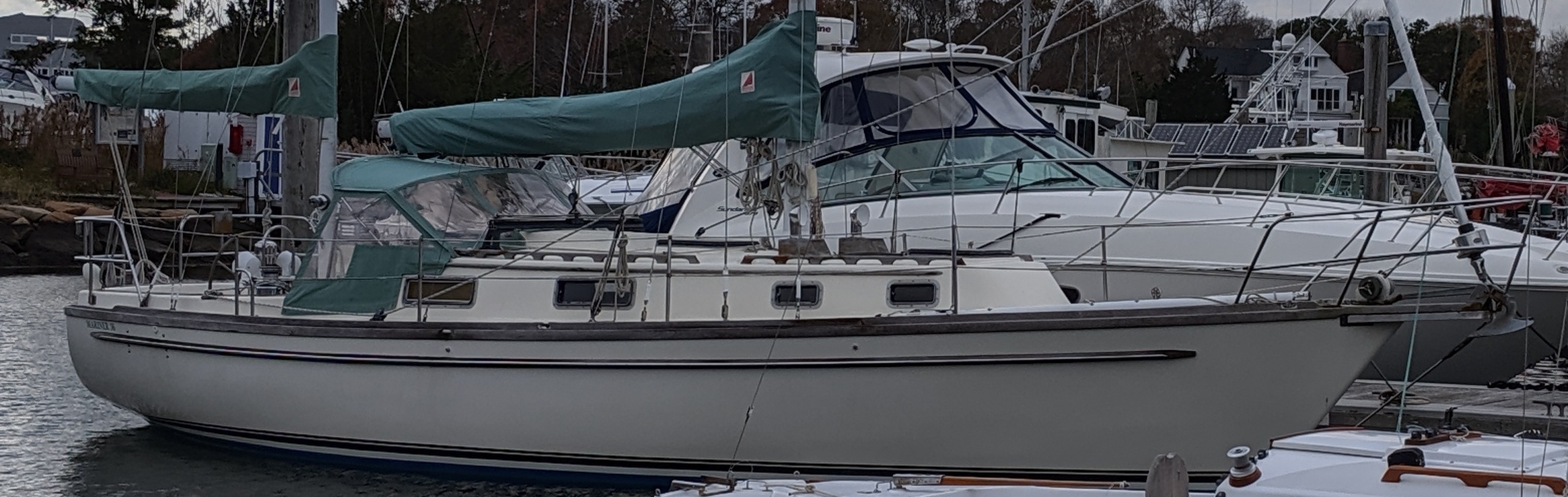
Original Wiring
After considering a partial rewire it became clear that very little if any of the original wire would remain, nearly all would be removed, and accomodating new wiring in the old circuit panel was close to hopeless.
Diesel related wiring
With the removal of the diesel engine quite a bit of electrical wiring is no longer needed. This includes key switch, temperature sensor, diesel tank level, and tachometer. These wires have been removed.
Engine driven refrigeration wiring
The engine driven refrigeration was added by a previous owner. This is likely to have been contracted to a professional as it was well done. Regardless the refrigeration wiring differs for a modern electrical refrigeration system. This wiring was also removed early in the process.
Original battery and charging wiring
The original house battery bank was a single 12V 125AH AGM deep cycle battery. In addition there was a 12V starter battery. Both of these batteries have been removed. The original house bank was charged by the alternator and trickle charged by a 100W solar panel. A Xantrax Echo charger was used to provide charging for the starter battery.
Wires for the original solar charger and battery monitor have been be removed. The battery monitor will be replaced with a set of shunts for charging and load on the 48V, 24V, and 12V banks. The original solar charge controller will also be replaced as it is a PWM controller rather than MPPT. There may be no use for the original Xantrex Echo Charger that isolates the two original 12V batteries. All of the wiring associated with the house and starter batteries and charging have been removed.
Original instrument wiring
The original depth and speed instruments were Datamarine models that were likely installed at build time. The depth instrument was analog with old and corroded coax cables to the transducer. The speed instrument had a clicker style knotlog installed in the navigation station. The wind instrument was also Datamarine and added later, but still very old. The radar was an ancient Furuno with CRT display. None of these instruments are networked since most were early 1980s vintage.
The wind instrument and tachometer were in a terrible location, on the forward wall of the cockpit footwell. If anyone were sitting or standing in the cockpit their legs would obscure visibility. This also seems to be a bad place to put holes in the cockpit.
The GPS was a Garmin 182C, a portable unit mounted when needed to the steering pedestal bars. This is a poor solution for this size boat and while perhaps the most recent instrument is also not capable of networking.
A decision was made to replace all of the original instruments and so with them the wiring. They have all been removed and the wiring removed. Holes for the wind instrument and tachometer have been patched.
Original Breaker Panel Enclosure and Wiring
The original breaker panel had a small number of DC circuits plus a small number of AC circuits connected directly to shore power. No AC charger and no inverter was installed. There were no high amperage loads which is a good thing since the battery bank was a single 12V 100Ah AGM battery.
It would have been possible to reuse the breaker panel enclosure with updated breaker panels but it would have been an extremely tight fit if it would fit at all. The 24V and 12V banks complicate the panel layout. A single positive bus can't be used. Due to the prioritization of 24V and 12V loads the new design requires five positive bus bars. Small loads such as the NAV switches, anchor light and overall circuits such as cabin lighting, domestic water pumps and instruments will be controlled by switches on the panel. Some larger loads such as water heaters, watermaker and the 24V inverters will have a breaker that only serves to operate a solenoid. Finer fusing on loads will be accomodated by individual fuses located closer to the load.
The low amperage breaker panel will be simplified. Mystery switches, such as "Loran" will be eliminated. Loads installed by previous owners that bypass the panel such as VHF will be put on the panel (for example, VHF would be connected to "instruments" on the panel but have its own fuse). The original enclosure will not be used.
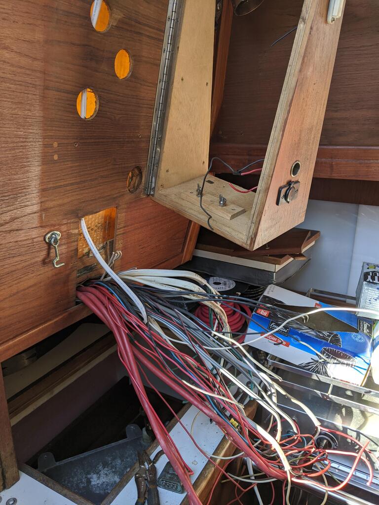
The original electrical panel enclosure is a teak shallow box with a 17" high by 10" wide openning and is mounted on the port side above the ice box. It is hinged for access to the wiring with the hinge on the port side. Wiring behind the panel was very tight. It is set up for two batteries with an A, B, A+B switch and analog voltmeter. The battery switch and meter takes up a lot of room and the battery switch requires bringing battery cables into the box. There is very limited room behind the box for wiring. The cabinetry slopes back at the bottom so the panel is deeper at the bottom. This creates a head strike hazard when accessing the ice box.
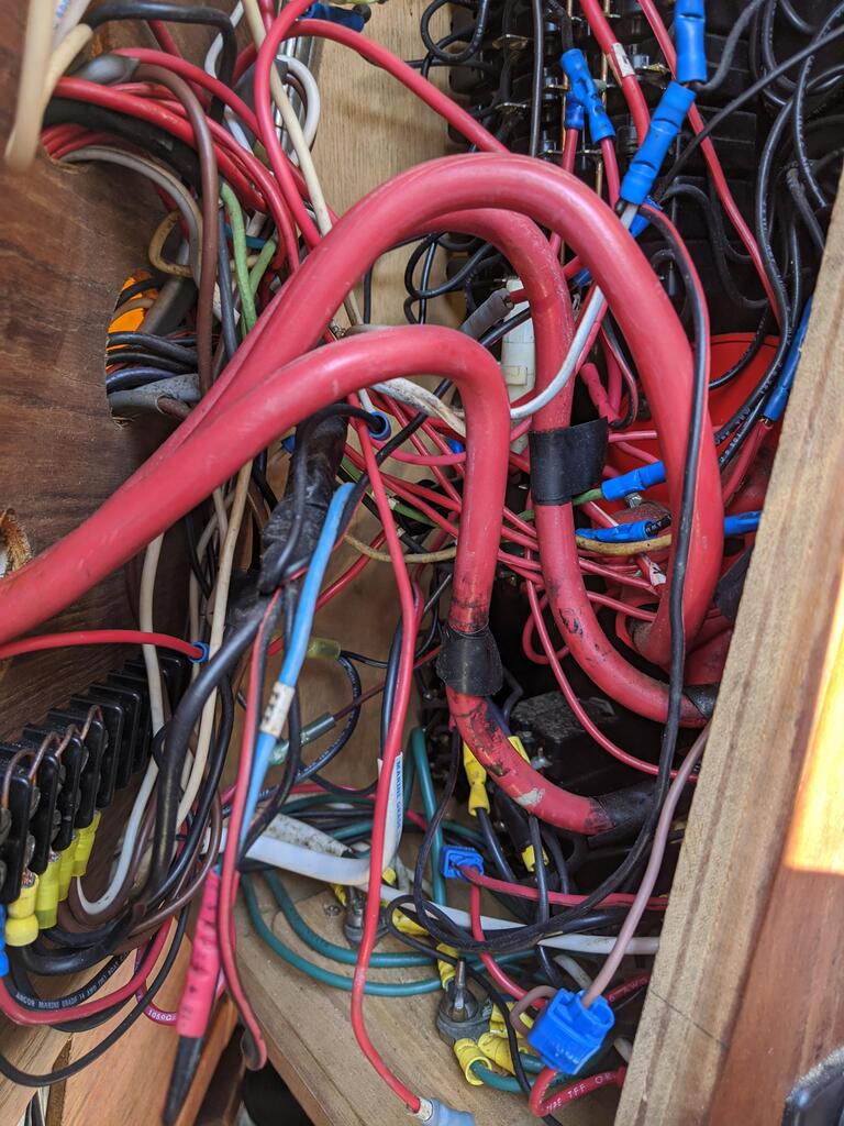
The original breaker panel wiring resembled spagetti. None of the wires were routed near the hinge, including the battery cables so the box could barely be openned and closed. Many of the wires were too small for the breaker size and some used automotive wire. There were numerous butt connectors and some automotive crimp connectors.
Currently there are only hole saw cutouts for the wires. Depth may be an issue on the shallower upper part but the existing enclosure. Part of the cabinetry may be cut out behind the circuit panel box to improve depth and reduce wire bends.
Original wiring routing and quality
Many of the original wires were run down the center of the engine compartment, through the bilge, and either further aft or under the cabin sole to either side near the aft end of the water tanks. This put electrical wire in the bilge and tie wrapped to the fresh water lines. Even AC wires were routed through the bilge.
On the port side there are very good alternative wiring routes along the cabin sides behind cabinetry. On the starboard side wire routing is a bit more difficult due to the navigation station. Small load wiring can be run in the space that is above the cabinetry and below the side decks. This might be tight for high load wires but fine for smaller low load wires.
The manufacturer's wiring quality was very poor. Wire sizes were small. Many wires are duplex with red and black inside a grey cover with some red and brown in a white cover. None of the wires were marked. In many places wires were bundled with what seems to be masking tape or some other paper based tape which had long ago deteriorated.
Most of the previous owner's wiring was worse than the manufacturer. The VHF was tied directly to the battery. Wire nuts and electrical tape were used to connect wires including AC wiring. AC wiring added by a previous owner used household NM-B solid conductor wire. DC wiring added by a previous owner was often spliced into an unrelated existing pairs of wires.
The wires on the circuit panel were soldered on. The circuit panel also had the 12V dual battery switch. Replacing the panel has become a priority partially due to the unworkable spagetti wiring. The new circuit panel will have three priorities of 12V and two priorities of 24V using solenoids to shed less essential loads if battery SoC drops.
Some of the circuit panel wiring has not been removed since it is inaccessible until the ice box is modified or replaced.
Gas locker solenoid and stove wiring
The decision to replace the gas range with an induction cooktop and electric oven makes the wiring associated with the gas locker solenoid no longer needed. Removing this wiring is ongoing since accessibility is limited.